Inductor

A technology of inductors and external electrodes, applied in the field of inductors, can solve the problems of reduced insulation and inability to obtain sufficient withstand voltage performance, and achieve sufficient withstand voltage performance

Active Publication Date: 2021-01-19
MURATA MFG CO LTD
View PDF7 Cites 1 Cited by
  • Summary
  • Abstract
  • Description
  • Claims
  • Application Information

AI Technical Summary

Problems solved by technology

[0004] It is known that the magnetic powder has an insulating film, but in the magnetic body formed by heating and compressing in the mold, especially in the area near the inner surface of the mold, the insulation performance is reduced
As a result, the insulation between the external electrodes of the inductor decreases, and when used in applications where a large current flows, sufficient withstand voltage performance may not be obtained.

Method used


Image

  • Inductor
  • Inductor
  • Inductor

Examples


no. 1 approach

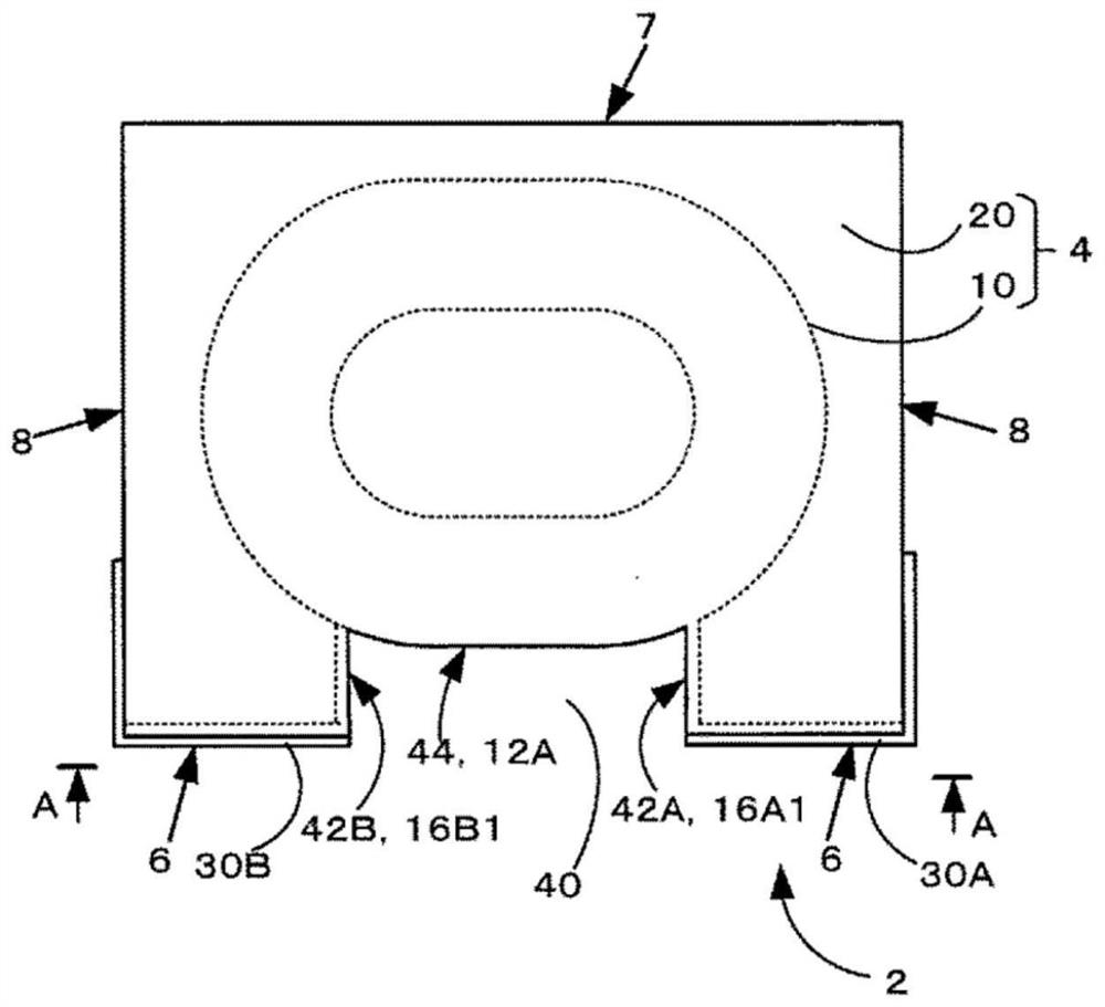
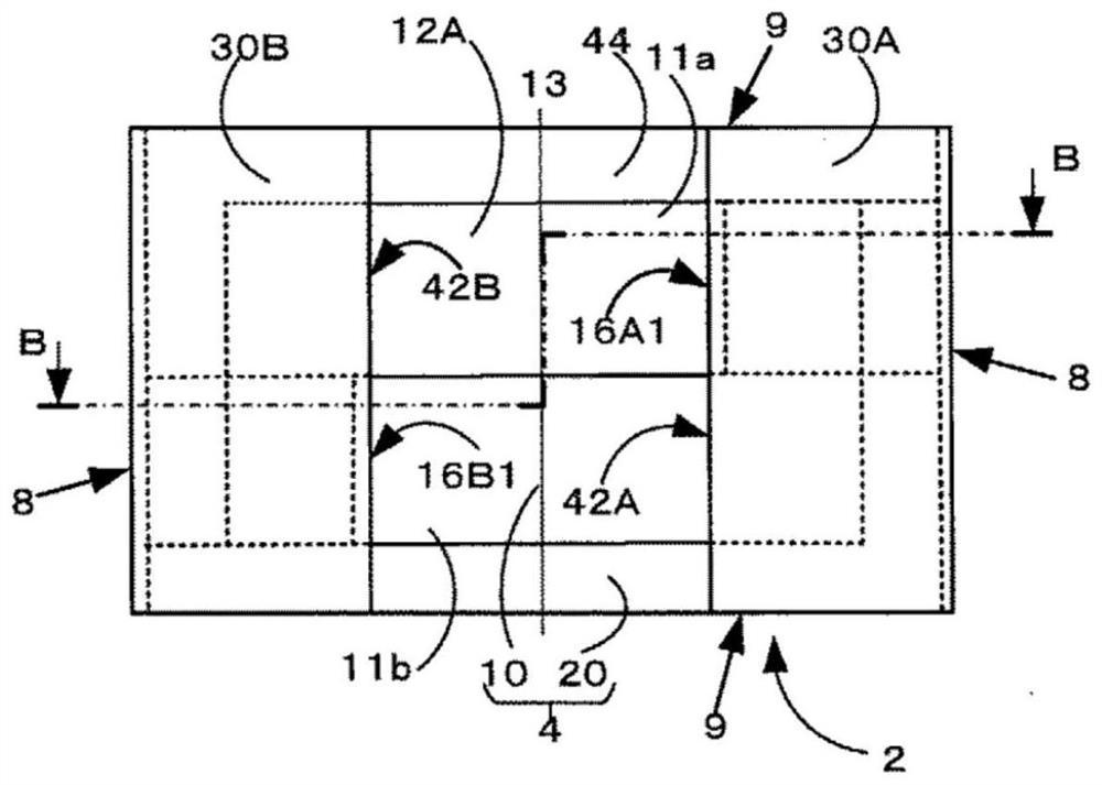
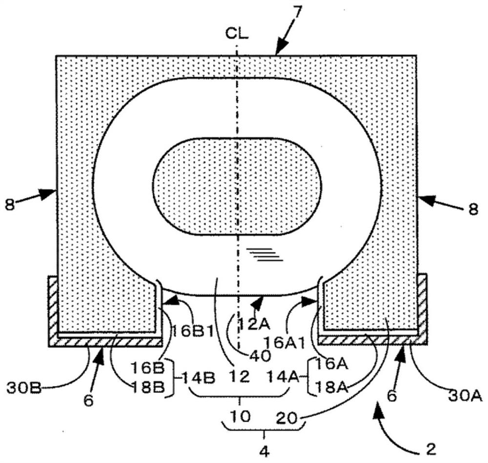
[0037] First, refer to Figure 1A , Figure 1B as well as Figure 1C The inductor according to the first embodiment of the present invention will be described. Figure 1A It is a side view schematically showing the outer shape of the inductor according to the first embodiment of the present invention. Figure 1B is a schematic representation of the mounting surface side of the inductor Figure 1A Bottom view of arrow A-A. Figure 1C is a schematic representation Figure 1B Side sectional view of section B-B. In addition, in Figure 1C , shows cross sections at different height positions on the left and right of the central line CL.

[0038] The inductor 2 according to the present embodiment includes a base body 4 having a substantially rectangular parallelepiped shape, and the base body 4 has a coil 10 and a magnetic body 20 that seals the coil 10 . The magnetic body 20 is made of magnetic powder and resin. The inductor 2 is a surface-mounted device having a mounting sur...

no. 2 approach

[0085] Next, refer to Figure 3A , Figure 3B as well as Figure 3C An inductor according to a second embodiment of the present invention will be described. Figure 3A It is a side view schematically showing the outer shape of the inductor according to the second embodiment of the present invention. Figure 3B is a schematic representation of the mounting surface side of the inductor Figure 3A Bottom view of the arrow E-E, Figure 3C is a schematic representation Figure 3B A side sectional view of section F-F. Figure 3C also with Figure 1C Similarly, the area on the right represents the winding portion 12 from which one lead-out portion 14A is drawn out. Figure 3B The cross-section of the segment 11a on the middle and upper side, the area on the left represents the winding portion 12 from which the other lead-out portion 14B is drawn out. Figure 3B The cross-section of the section 11b on the middle and lower side.

[0086] The second embodiment is different from...

no. 3 approach

[0090] Next, refer to Figure 4A , Figure 4B as well as Figure 4C An inductor according to a third embodiment of the present invention will be described. Figure 4A It is a side view schematically showing the outline of the inductor according to the second embodiment of the present invention, Figure 4B is a schematic representation of the mounting surface side of the inductor Figure 4A The bottom view of the arrow C-C, Figure 4C is a schematic representation Figure 4B Side cutaway view of section D-D. Figure 4C also with Figure 1C Similarly, the area on the right represents the winding portion 12 from which one lead-out portion 14A is drawn out. Figure 4B The cross-section of the segment 11a on the middle and upper side, the area on the left represents the winding portion 12 from which the other lead-out portion 14B is drawn out. Figure 4B The cross-section of the section 11b on the middle and lower side.

[0091] In the third embodiment, the difference from...


PUM

PropertyMeasurementUnit
lengthaaaaaaaaaa
lengthaaaaaaaaaa
heightaaaaaaaaaa

Abstract

The invention relates to an inductor. The inductor includes an element assembly and a pair of outer electrodes. The element assembly includes a coil and a magnetic body. The coil includes a winding portion in which conductive wires each having a coating layer are spirally wound in two stages connected at their innermost segments and a pair of extension portions extended from their outermost segments in the stages of the winding portion. The magnetic body has a mounting surface, is made of magnetic powder and resin, and seals the coil such that the mounting surface is approximately parallel with a winding axis of the winding portion. The outer electrodes are disposed on the mounting surface. Each of the extension portions includes a first region and a second region. The element assembly hasa recess portion allowing the first regions and an outer surface of the winding portion positioned between the first regions to be exposed.

Description

technical field [0001] The present invention relates to inductors, particularly inductors of the surface mount type. Background technique [0002] Surface mount inductors having coils and magnetic bodies that seal coils are widely used. Among them, an inductor has been proposed in which the winding axis of the coil is parallel to the mounting surface, the lead-out portion of the coil is drawn to the surface of the mounting surface, and an external electrode is formed thereon (for example, refer to Patent Document 1). In the inductor described in Patent Document 1, a preform made of magnetic powder and resin incorporating a coil is placed in a mold, and the magnetic body is formed by compressing and raising the temperature. [0003] Patent Document 1: International Publication No. 2017 / 188102 [0004] It is known that magnetic powder has an insulating film, but in a magnetic body formed by heating and compressing in a mold, especially in a region near the inner surface of t...

Claims


Application Information

Patent Timeline
Patent Type & Authority Applications(China)
IPC IPC(8): H01F17/04H01F27/255H01F27/28H01F27/29H01F27/30H01F27/32H01F41/00H01F41/02
CPCH01F17/04H01F27/255H01F27/2847H01F27/292H01F27/324H01F27/306H01F41/00H01F41/0246H01F2017/048H01F27/323H01F41/063H01F27/2852H01F27/2823H01F27/24H01F27/29
Inventor 渡边亮太
Owner MURATA MFG CO LTD
Why Eureka
Try Eureka