Transformer heat dissipation shell

A heat dissipation shell and transformer technology, which is applied in the field of transformers, can solve the problems of transformer influence, electronic components burnout, etc., and achieve the effect of ensuring normal operation, long service life and good heat dissipation performance

Pending Publication Date: 2021-01-19
武汉九控电气科技有限公司
View PDF5 Cites 0 Cited by
  • Summary
  • Abstract
  • Description
  • Claims
  • Application Information

AI Technical Summary

Problems solved by technology

There are many electronic components installed in the transformer, which will generate a lot of heat during the working process. If the heat cannot be dissipated in time

Method used


Image

  • Transformer heat dissipation shell
  • Transformer heat dissipation shell
  • Transformer heat dissipation shell

Examples


Embodiment Construction

[0014] The following will clearly and completely describe the technical solutions in the embodiments of the present invention with reference to the accompanying drawings in the embodiments of the present invention. Obviously, the described embodiments are only some, not all, embodiments of the present invention. Based on the embodiments of the present invention, all other embodiments obtained by persons of ordinary skill in the art without making creative efforts belong to the protection scope of the present invention.

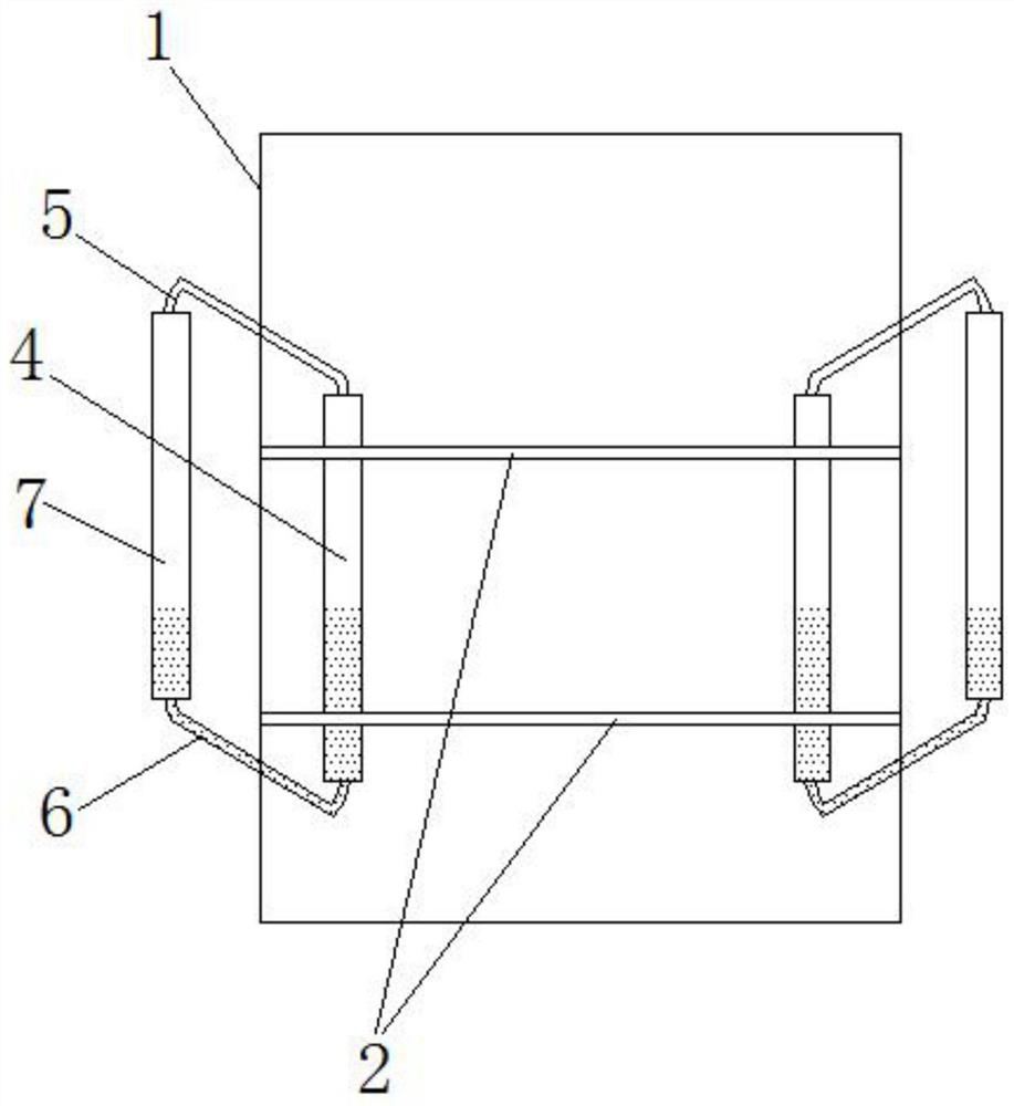
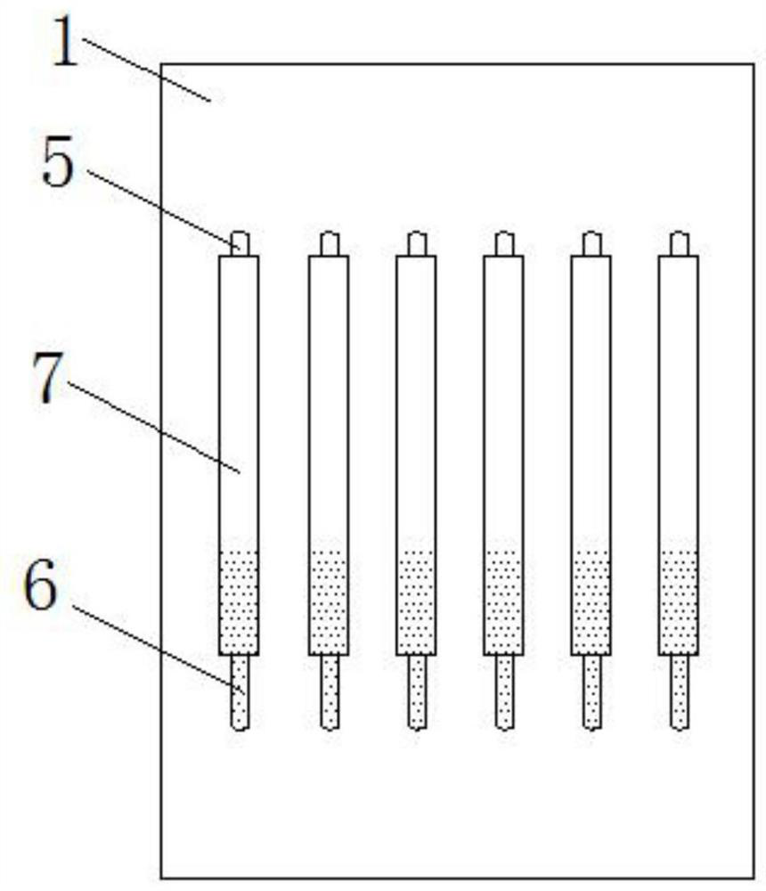
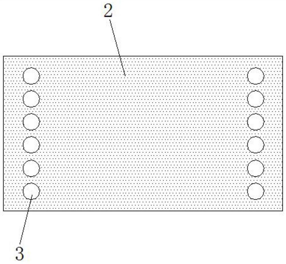
[0015] see Figure 1-3 , the present invention provides a technical solution: a transformer heat dissipation shell, including a square box shell 1, the box shell 1 is horizontally provided with two layers of heat conduction plates 2, and the left and right sides of the heat conduction plate 2 are all along the width direction of the box shell 1 There are a plurality of side-by-side round ports 3, and each round port 3 is fixed with a vertical inner glass tube ...


PUM


Abstract

The transformer heat dissipation shell comprises a square box shell, the box shell is transversely provided with an upper heat conduction plate and a lower heat conduction plate, the left side and theright side of each heat conduction plate are each provided with a plurality of side-by-side round openings in the width direction of the box shell, and a vertical inner glass pipe perpendicular to the corresponding heat conduction plate is fixed in each round opening; the tops and the bottoms of the inner glass tubes are connected with steam tubes and return tubes correspondingly, the steam tubesand the return tubes are obliquely and upwards connected to the exterior of the box shell, and the left side and the right side of the exterior of the box shell are provided with outer glass tubes which are parallel to the inner glass tubes on the left side and the right side of the heat conduction plate and correspond to the same in terms of quantity. The ends, located outside the box shell, ofthe steam pipe and the return pipe are connected to the top and the bottom of the outer glass pipe respectively; the inner glass pipe is filled with condensate water. The shell conducts heat generatedby working of electronic components of the transformer to the inner glass tube through the heat conduction plate, condensate water in the inner glass tube absorbs heat and is vaporized into steam, and the steam is conveyed to the outside through the steam tube to be subjected to heat release vaporization and conducted to the outside.

Description

technical field [0001] The invention relates to the technical field of transformers, in particular to a heat dissipation shell of a transformer. Background technique [0002] The transformer is a facility used to change the power supply voltage. The high-voltage electricity transmitted by the high-voltage cable can be converted into the commonly used 220V voltage by the transformer through the action of the transformer. There are many electronic components installed in the transformer, which will generate a lot of heat during the working process. If the heat cannot be dissipated in time, once the temperature in the transformer case is too high, it will affect the normal operation of the transformer, and even cause the electronic components to burn out. . Contents of the invention [0003] The purpose of the present invention is to provide a new type of transformer casing, which has good heat dissipation performance and can dissipate the heat generated during the operation...

Claims


Application Information

Patent Timeline
IPC IPC(8): H01F27/02H01F27/18H01F27/22
CPCH01F27/025H01F27/18H01F27/22
Inventor 郑霖
Owner 武汉九控电气科技有限公司
Why Eureka
Try Eureka