
Metal surface treatment spraying device with continuous spraying and horizontal movement structure and operation method thereof

A technology for metal surface treatment and spraying device, which is applied to the device for coating liquid on the surface, the spraying device, the pretreatment surface, etc., which can solve the problems of the dead angle of the sprayed object, the poor working quality of the spraying device, and the difficulty of spraying the spraying device. , to achieve the effect of improving work efficiency and reducing dead ends of spraying

Inactive Publication Date: 2021-01-22
芜湖天锐捷精密电子设备有限公司
View PDF0 Cites 0 Cited by
  • Summary
  • Abstract
  • Description
  • Claims
  • Application Information

AI Technical Summary

Problems solved by technology

[0003] During the working process of the current spraying device, there are some dead angles on the sprayed objects, so that the spraying device is difficult to spray, which affects the overall work quality and speed, and the current spraying device has poor working quality, and the pre-order work needs to be completed manually before spraying. ,waste time

Method used


Image

  • Metal surface treatment spraying device with continuous spraying and horizontal movement structure and operation method thereof
  • Metal surface treatment spraying device with continuous spraying and horizontal movement structure and operation method thereof
  • Metal surface treatment spraying device with continuous spraying and horizontal movement structure and operation method thereof

Examples


Embodiment 1

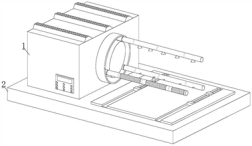
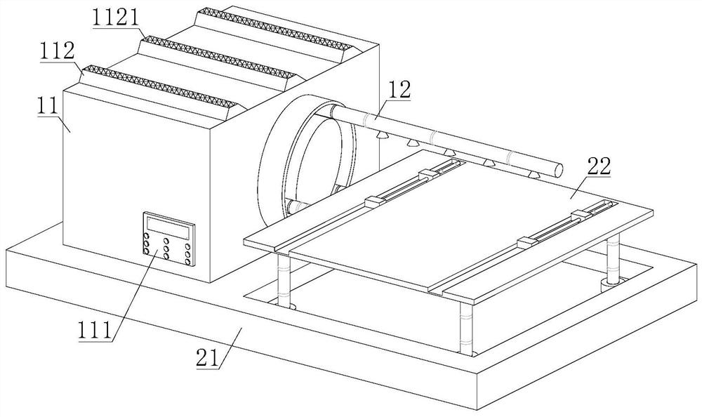
[0030] refer to figure 1 , 2 And 7, a metal surface treatment spraying device with a continuous spraying translation structure, including an operating mechanism 1 and a supporting mechanism 2, the upper end of the supporting mechanism 2 is provided with an operating mechanism 1, and the operating mechanism 1 includes a box body 11 and a spraying mechanism 12, One side of the box body 11 is provided with a spraying mechanism 12, the spraying mechanism 12 is connected with the support mechanism 2 through the box body 11, the box body 11 includes a control panel 111, an end block 112, an air pump A113, a motor 114, an air pump B115 and a connecting pipe 116 , a control panel 111 is fixedly installed on the outer surface of the box body 11, an end block 112 is fixedly installed on the upper surface of the box body 11, a heat dissipation grid 1121 is arranged on the upper surface of the end block 112, and the air pump A113, the motor 114 and the air pump B115 are all set Inside th...

Embodiment 2

[0032] refer to Figure 5 and 6, the spraying mechanism 12 comprises fixed disk 121, spraying pipe 122, grinding pipe 123, air blowing pipe 124 and fixture 125, one side of fixed disk 121 is provided with spraying pipe 122, grinding pipe 123 and blowing pipe 124, spraying pipe 122, grinding One end of pipe 123 and air blowing pipe 124 is all provided with fixture 125, and one side of fixed disc 121 is provided with arc groove 1211, and spraying pipe 122, polishing pipe 123 and air blowing pipe 124 are all connected with arc groove 1211 by fixture 125. Connection, the outer surface of the spray pipe 122 is provided with a continuous nozzle 1221, one end of the continuous nozzle 1221 is provided with a threaded joint 1222, the continuous nozzle 1221 is movably connected with the spray pipe 122 through the threaded joint 1222, and the outer surface of the grinding pipe 123 is provided with a frosting layer 1231, the outer surface of the air blowing pipe 124 is provided with an a...

Embodiment 3

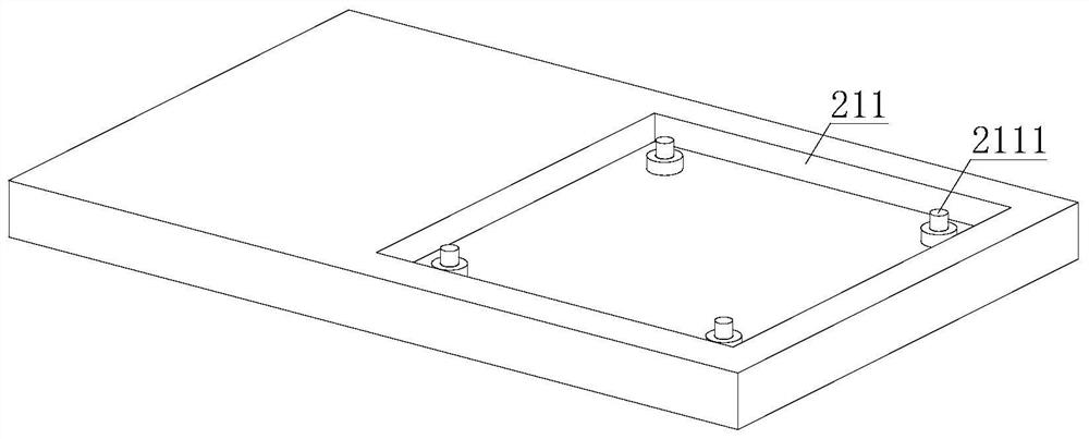
[0034] refer to image 3 , 4 And 7, the output end of motor 114 is provided with curved rod 1141 and straight rod 1142, and motor 114 is connected with fixture 125 by curved rod 1141, and motor 114 is connected with grinding tube 123 by straight rod 1142, and motor 114 is connected with external power supply. The motor 114 is connected with the control panel 111 signal, one end of the air pump B115 is provided with an air pipe 1151, the other end of the air pump B115 communicates with the outside world, the air pump B115 communicates with the blowing pipe 124 through the air pipe 1151, and one end of the communication pipe 116 It is connected with the spraying pipe 122, the other end of the connecting pipe 116 is connected with the external paint, the air pump A113 is connected with the outer surface of the connecting pipe 116, the air pump A113 and the air pump B115 are connected with the control panel 111 for signals, and the upper surface of the bottom plate 21 is provided ...


PUM


Abstract

The invention discloses a metal surface treatment spraying device with a continuous spraying and horizontal movement structure and an operation method thereof. The metal surface treatment spraying device with the continuous spraying and horizontal movement structure aims at solving the problems that in the working process of an existing spraying device, some dead angles exist on sprayed objects, so that it is difficult for the spraying device to spray the dead angles, and then the overall working quality and speed are influenced; and the working quality of the existing spraying device is poor,pre-spraying work needs to be completed manually before spraying, and time is consumed. According to the metal surface treatment spraying device with the continuous spraying and horizontal movement structure and an operation method thereof, supporting movable blocks are made to move left and right through telescopic rods, continuous spray heads are arranged on the outer surface of a spraying pipe, the spraying pipe is a telescopic pipe, and all the surfaces of an object can be sprayed without dead corners; and meanwhile, a grinding pipe and an air blowing pipe are further arranged, pre-grinding can be conducted before spraying, after grinding, the surface of the object can be blown clean through the air blowing pipe, on one hand, the object spraying quality is greatly improved, and on theother hand, the working efficiency is improved.

Description

technical field [0001] The invention relates to the technical field of metal surface treatment equipment, in particular to a metal surface treatment spraying device with a continuous spraying translation structure and an operation method thereof. Background technique [0002] Spraying equipment is the product of the environment where automation is becoming more and more common in the development of industrial technology after the reform and opening up. As the degree of automation becomes higher and higher, the application of spraying production lines is becoming more and more extensive, and it has penetrated into the national economy. In many fields, the spraying equipment on the market can be divided into three types according to the degree of automation: manual spraying equipment, semi-automatic spraying equipment and fully automatic spraying equipment. With the development of industrial technology, pure handwork can no longer meet the needs of the market. Spraying has bee...

Claims


Application Information

Patent Timeline
Patent Type & Authority Applications(China)
IPC IPC(8): B05B16/20B05B13/02B05D3/04B05D3/12B24B7/10B24B41/06
CPCB05B13/0221B05D3/0406B05D3/12B24B7/10B24B41/068B05B16/20
Inventor 董晨吴国友吴义涛
Owner 芜湖天锐捷精密电子设备有限公司
Learn More