On-rail tooling system for truss assembly with variable scale and complex configuration

A variable-scale and complex technology, applied in metal processing, manufacturing tools, metal processing equipment, etc., can solve the problems of slow lap joint efficiency, complicated control, low safety, etc., and achieve less driving, large folding ratio, and structural compact effect

Active Publication Date: 2021-08-27
YANSHAN UNIV +1
View PDF8 Cites 0 Cited by
  • Summary
  • Abstract
  • Description
  • Claims
  • Application Information

AI Technical Summary

Problems solved by technology

There are many ways to realize the construction of upright structures. Most of the overlapping methods proposed so far are to install the truss on the base, and complete the on-orbit overlapping by multiple small robots, which effectively solves the problems caused by manual assembly of astronauts. low safety, low efficiency, and high resource consumption. However, when it is used to overlap large and complex structures, it needs to go back and forth to fetch materials multiple times, which makes the efficiency of lapping slower and the control is complicated. It is still difficult to achieve; in addition In addition, there is another lap joint method, which is to first fix multiple truss joints on the base in sequence, then connect the truss rods between the joints to form a truss sub-unit structure, and then splice several sub-unit structures to achieve multiple The splicing of truss structures of various specifications, but there is no auxiliary tooling equipment for this method

Method used


Image

  • On-rail tooling system for truss assembly with variable scale and complex configuration
  • On-rail tooling system for truss assembly with variable scale and complex configuration
  • On-rail tooling system for truss assembly with variable scale and complex configuration

Examples


Embodiment Construction

[0051] In order to detail the technical content, structural features, achieved goals and effects of the present invention, the following will be described in detail in conjunction with the accompanying drawings.

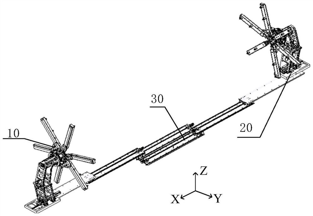
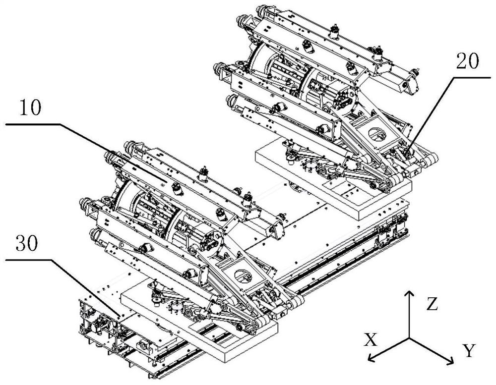
[0052] The on-rail tooling system for truss assembly with variable scale and complex configuration provided by the present invention, such as figure 1 and figure 2 As shown, it includes an installation planar mechanism 10, a folding support mechanism 20 and a drawer bottom plate mechanism 30. The two folding support mechanisms 20 are respectively installed at opposite ends of the same side of the drawer bottom plate mechanism 30. The two installation plane mechanisms 10 are respectively It is relatively installed on the inner side of the upper part of the two folding support mechanisms 20 .

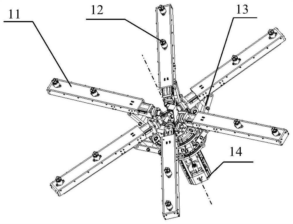
[0053] Such as image 3 As shown, the installation plane mechanism 10 includes a head frame 14, a movable support arm 11, a push-up support arm 13 and a head fixing lock 12, ...


PUM


Abstract

The invention relates to an on-rail tooling system for truss assembly with variable scale and complex configuration, which includes a mounting plane mechanism, a folding support mechanism and a drawing bottom plate mechanism, and the two folding support mechanisms are respectively installed on two sides on the same side of the drawing bottom plate mechanism. Two installation plane mechanisms are respectively installed on the inner sides of the upper parts of the two folding support mechanisms. The installation plane mechanism includes the head frame, the movable support arm, the push-up support arm and the head fixed lock. , the middle floor, the bottom floor and the turntable bearing, the installation plane mechanism, the folding support mechanism and the drawing bottom plate mechanism can all be folded and unfolded by themselves. The invention has the advantages of large folding-expanding ratio, fewer drives, compact structure, etc., and can assist tooling equipment for high-precision on-rail assembly of various complex configuration trusses.

Description

technical field [0001] The invention belongs to the field of on-rail assembly tooling equipment, and in particular relates to an on-rail tooling system for truss assembly with variable scale and complex configuration. Background technique [0002] With the development of aerospace technology, the demand for large-scale space structures continues to increase. However, due to the limited loading capacity provided by vehicles, heavy-duty or large-scale space structures must be assembled in space. [0003] The on-orbit construction methods of large-scale space structures mainly include three types: expandable structure construction, space-forming structure construction and upright structure construction. application. There are many ways to realize the construction of upright structures. Most of the overlapping methods proposed so far are to install the truss on the base, and complete the on-orbit overlapping by multiple small robots, which effectively solves the problems caused...

Claims


Application Information

Patent Timeline
Patent Type & Authority Patents(China)
IPC IPC(8): B23P19/00
CPCB23P19/00
Inventor 姚建涛许焕宾张敬尧成志忠党政李德勇周玉林曾福明赵永生施丽铭
Owner YANSHAN UNIV
Why Eureka
Try Eureka