
Automatic polishing device for inner surface of traffic signal lamp reflector

A traffic signal light and inner surface technology, applied in the direction of grinding drive device, optical surface grinder, grinder, etc., can solve the problems of uneven polishing of the inner wall of the reflector, affecting the quality of the signal light, increasing labor costs, etc., to improve production efficiency, The effect of avoiding worker injuries and reducing labor costs

Inactive Publication Date: 2021-01-22
福州中天泰电子科技有限公司
View PDF0 Cites 0 Cited by
  • Summary
  • Abstract
  • Description
  • Claims
  • Application Information

AI Technical Summary

Problems solved by technology

[0002] The indicator light is a device that uses light to monitor the working or position status of circuits and electrical equipment. It is usually used to reflect the working status and position status of circuits and equipment. In the production process of traditional traffic lights, it is necessary to polish the reflector. Nowadays, most Grinding the reflector manually is not only inefficient and takes a long time, but also has no control over manual grinding, which will cause the inner wall of the reflector to be polished unevenly and affect the quality of the signal light. On the other hand, manual grinding will increase the labor cost. Cost, when grinding manually, there may be a hidden danger of injury to workers

Method used


Image

  • Automatic polishing device for inner surface of traffic signal lamp reflector
  • Automatic polishing device for inner surface of traffic signal lamp reflector
  • Automatic polishing device for inner surface of traffic signal lamp reflector

Examples


Embodiment Construction

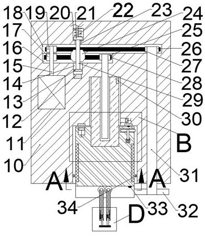
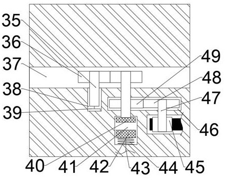
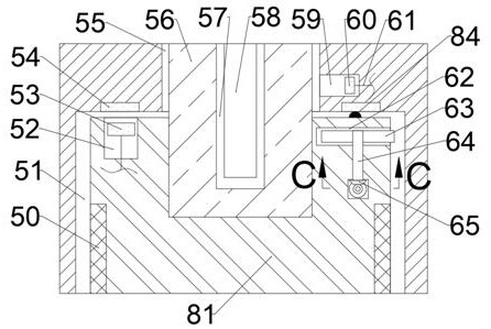
[0018]Combine belowFigure 1-5The present invention will be described in detail, in which, for the convenience of description, the following directions are specified as follows:figure 1 The projection relationship itself has the same up, down, left, and front directions.

[0019]An automatic polishing device for the inner surface of a traffic signal light reflector described in conjunction with FIGS. 1-5 includes a main box body 10 in which a rotating block cavity 51 with a downward opening is provided, and the rotating block cavity The upper side of 51 is connected with a telescopic rod cavity 55, the right side of the telescopic rod cavity 55 is connected with a secondary magnetic block cavity 59, and the upper side of the telescopic rod cavity 55 is provided with a screw belt cavity 16 extending to the left. The upper side of the screw belt cavity 16 is connected with a motor belt cavity 18 extending to the right. The upper side of the motor belt cavity 18 is connected with an index ...


PUM


Abstract

The invention relates to the related field of indicating lamps, and discloses an automatic polishing device for the inner surface of a traffic signal lamp reflector. The automatic polishing device comprises a main box body, a rotating block cavity with a downward opening is formed in the main box body, the upper side of the rotating block cavity is provided with a telescopic rod cavity in a communicating mode, and the right side of the telescopic rod cavity is provided with an auxiliary magnetic block cavity in a communicating mode. A lead screw belt cavity extending leftwards is formed in theupper side of the telescopic rod cavity. According to the automatic polishing device, a friction wheel is driven by a rotating block to move up and down, so that the friction wheel can perform automatic continuous operation, the polishing time of the traffic signal lamp reflector is greatly shortened, and the manufacturing efficiency of a traffic signal lamp is improved; and then through rotationof the rotating block, the friction wheel polishes the inner wall of the reflector, meanwhile, a friction wheel fixing rod is opened, so that the reflector is polished more thoroughly, force is exerted evenly, and the problem that polishing is too heavy or too light is avoided. On the other hand, the automatic polishing device is operated automatically, the labor cost is reduced, and meanwhile the hidden danger that workers are injured is also avoided.

Description

Technical field[0001]The invention relates to the related field of indicator lights, in particular to an automatic polishing device for the inner surface of a traffic signal light reflector.Background technique[0002]Indicator lights are devices that use lights to monitor the working or position status of circuits and electrical equipment. They are usually used to reflect the working status and position status of circuits and equipment. Traditional traffic signal lights need to be polished and polished during the production process. Manual polishing of the reflector is used. This not only has low polishing efficiency and long polishing time, but also has no control on manual polishing, which will result in uneven polishing of the inner wall of the reflector and affect the quality of the signal light. On the other hand, manual polishing will increase labor Cost, when manually polished, there may be a hidden danger of injury to workers.Summary of the invention[0003]The purpose of the p...

Claims


Application Information

Patent Timeline
Patent Type & Authority Applications(China)
IPC IPC(8): B24B13/00B24B27/00B24B41/04B24B47/12B24B47/16B24B47/20
CPCB24B13/00B24B27/0076B24B41/04B24B47/12B24B47/16B24B47/20
Inventor 邓石
Owner 福州中天泰电子科技有限公司
Learn More