
Plastic processing granulator

A granulator and plastic technology, applied in the field of plastic processing machines, can solve problems such as water vapor cracks

Inactive Publication Date: 2021-01-22
邹子昊
View PDF0 Cites 0 Cited by
  • Summary
  • Abstract
  • Description
  • Claims
  • Application Information

AI Technical Summary

Problems solved by technology

[0006] In order to solve the above-mentioned technology, when the granulated plastic material is heated and dissolved, the water vapor that emerges will be sandwiched between the materials during the process of the material being squeezed into the container and will not be absorbed by the material. When the bar is formed and output, cracks are generated in the position where the water vapor is trapped

Method used


Image

  • Plastic processing granulator
  • Plastic processing granulator
  • Plastic processing granulator

Examples


Embodiment 1

[0032] as attached figure 1 to attach Figure 6 Shown:

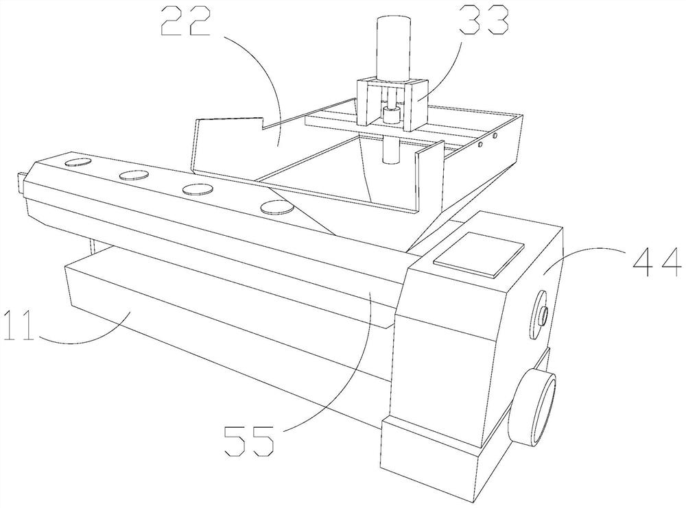
[0033] The present invention provides a plastic processing and granulating machine, the structure of which comprises a bottom box 11, a hopper 22, a stirring head 33, a pressure box 44, and a molding box 55. The bottom box 11 is installed below the molding box 55 and is parallel to each other. The stirring head 33 is welded on the inner surface of the hopper 22 , the hopper 22 is fixed on the upper surface of the forming box 55 and penetrates each other, and the forming box 55 and the pressure box 44 are welded and penetrated each other.

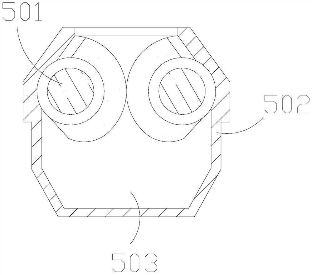
[0034] The forming box 55 includes a pressing body 501 , an outer frame 502 and an inner tank 503 , the pressing body 501 is movably connected with the outer frame 502 , and the inner tank 503 is installed inside the outer frame 502 .

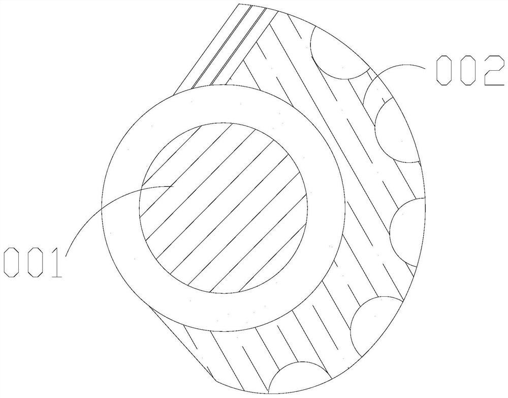
[0035] Wherein, the pressure body 501 includes a central shaft 001 and a curved body 002, the curved body 002 is fixed on the outer surface of the ce...

Embodiment 2

[0042] as attached Figure 7 to attach Figure 9 Shown:

[0043] Wherein, the central axis 001 includes an extension ring 511, an inner rubber ring 512, an extension body 513, and a pituitary body 514. The extension ring 511 is wrapped on the outer surface of the inner rubber ring 512, and the extension body 513 is connected with the extension ring 511. The pituitary 514 runs through the inside of the extension ring 511. The inner rubber ring 512 is made of rubber material and has a certain toughness. The extension ring 511 fixes the position of the overall outer frame. swing within the range.

[0044] Wherein, the pituitary gland 514 includes a main ball g11, a solid block g12, and a rubber strip g13, the rubber strip g13 is fixed between the main ball g11 and the solid block g12, the main ball g11 is a spherical structure, and the rubber strip g13 It is made of rubber material and has a certain toughness. The main ball g11 fixes the force point of the connection part, and...


PUM


Abstract

The invention discloses a plastic processing granulator which structurally comprises a bottom box, a hopper, a stirring head, a pressing box and a forming box. The bottom box is installed below the forming box and is parallel to the forming box, the stirring head is welded to the inner surface of the hopper, the hopper is fixed to the upper surface of the forming box and is communicated with the forming box, and materials can extrude and apply force to a pressing body in the extrusion process, so that an arc pressing body can rotate downwards along a middle shaft, the moving range of a joint part is fixed, foreign objects are extruded more comprehensively, a main pressing body makes large-area contact with the materials, extruded moisture can be sucked by an inner suction strip, after thematerials are heated and dissolved, generated water vapor is clamped between the materials, and the water vapor is extruded out before mold entering for forming; an extension ring extends to expand aninternal area, and an extension body can assist the arc pressing body in being pulled open, so that a fixed block of a vertical body drags a rotating part to move accordingly, movement can be done within a certain range when an internal part is stressed according to swing of the joint part within a certain range, and dragging back to an original position can be carried out in time.

Description

technical field [0001] The invention belongs to the field of plastic processing machines, and more specifically relates to a plastic processing granulator. Background technique [0002] After the whole plastic material is heated and dissolved, it can be piled up and input into the forming container. Through the internal extrusion force, it can be squeezed and formed in one direction, and it can be pelletized after cooling. [0003] Based on the above-mentioned inventor's discovery, the existing plastic processing granulator mainly has the following deficiencies, such as: [0004] When the granulated plastic material is heated and dissolved, the water vapor that emerges will be sandwiched between the materials during the process of the material being squeezed into the container and will not be absorbed by the material. , Cracks are generated at the position where the water vapor is trapped. [0005] Therefore need to propose a kind of plastic processing granulator. Conten...

Claims


Application Information

Patent Timeline
IPC IPC(8): B29B9/06B29C48/76
CPCB29B9/06B29C48/766
Inventor 邹子昊
Owner 邹子昊
Learn More