Self-snow-cleaning skylight of new energy automobile

A new energy vehicle and sunroof technology, which is applied in vehicle cleaning, vehicle maintenance, vehicle parts, etc., can solve the problems of driver's driving experience, affecting the lighting in the car, and inconvenient manual cleaning of snow on the sunroof, so as to promote snow melting , Improve snow clearing effect and good lighting effect

Inactive Publication Date: 2021-01-22
顾龙
View PDF7 Cites 1 Cited by
  • Summary
  • Abstract
  • Description
  • Claims
  • Application Information

AI Technical Summary

Problems solved by technology

[0003] The sunroof is an important part of new energy vehicles for lighting and ventilation. When the vehicle is driving on the road in snowy winter, snowflakes will gradually fall and cover the sunroof glass, blocking the light and affecting the lighting in the car. Most of the existing new energy vehicle sunroofs do not have an automatic snow removal function, and it is inconvenient for the driver to manually clear the snow on the sunroof when driving, which affects the driving experience of the vehicle and the driver

Method used


Image

  • Self-snow-cleaning skylight of new energy automobile
  • Self-snow-cleaning skylight of new energy automobile
  • Self-snow-cleaning skylight of new energy automobile

Examples


Embodiment 1

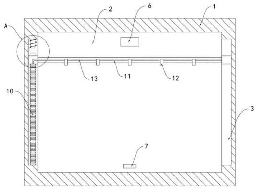
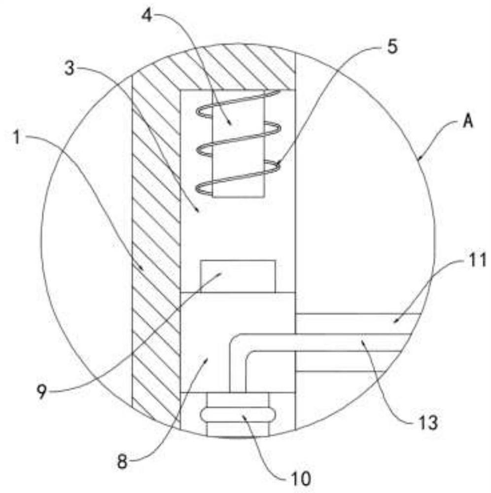
[0022] Such as Figure 1-3 As shown, a self-clearing sunroof of a new energy vehicle includes a frame body 1 and a skylight glass plate 2 installed in the frame body 1, and a chute 3 is opened on the inner ring side wall of the frame body 1, and the top of the chute 3 An electromagnet 4 is fixedly installed on the surface, and a spiral coil 5 is arranged around the electromagnet 4. A ceramic temperature difference sheet 6 and a photosensitive resistor 7 are embedded in the skylight glass plate 2. The positive and negative poles of the ceramic temperature difference sheet 6 pass through the photosensitive resistor 7 and the spiral Both ends of the coil 5 are electrically connected, a slider 8 slides in the chute 3, the upper end of the slider 8 is fixedly connected with a permanent magnet block 9, and the lower end of the slider 8 is fixedly connected with the bottom surface of the chute 3 through an elastic bellows 10, The surface of the skylight glass plate 2 is provided with...

Embodiment 2

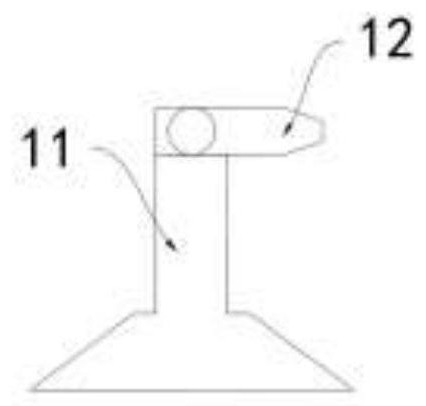
[0030] Such as Figure 4 As shown, the difference between this embodiment and Embodiment 1 is that the slider 8 and the snow cleaning strip 11 are both made of heat-conducting metal materials, and the inner wall of the chute 3 is equipped with a friction plate 14 that is in contact with the slider 8 .

[0031] In this embodiment, when the slider 8 slides in the chute 3, it rubs against the friction plate 14 and generates heat, and the heat is conducted by the slider 8 and the snow strip 11 to the snow accumulation on the surface of the skylight glass plate 2, further Promote snow melting and facilitate snow removal.


PUM


Abstract

The invention belongs to the field of new energy automobiles, and particularly relates to a self-snow-cleaning skylight of a new energy automobile. The self-snow-cleaning skylight comprises a frame body and a skylight glass plate installed in the frame body; a sliding groove is formed in the side wall of the inner ring of the frame body; an electromagnet is fixedly installed on the top face of thesliding groove; a spiral coil is wound around the electromagnet; a ceramic temperature difference piece and photoresistors are embedded in the skylight glass plate; the positive electrode and the negative electrode of the ceramic temperature difference piece are electrically connected with the two ends of the spiral coil through the photoresistors; a sliding block slides in the sliding groove; apermanent magnet is fixedly connected to the upper end of the sliding block, and the lower end of the sliding block is fixedly connected with the bottom face of the sliding groove through an elastic corrugated pipe. The ceramic temperature difference piece can generate electric energy through the temperature difference inside and outside the automobile to drive snow removing strips to scrape accumulated snow on the surface of the skylight glass plate, a driver does not need to remove snow manually, the good lighting effect in the automobile is guaranteed, other power supplies are not needed for power supply, and the environment-friendly concept of energy conservation and emission reduction of the new energy automobile is reflected.

Description

technical field [0001] The invention belongs to the field of new energy vehicles, in particular to a self-clearing snow sunroof of a new energy vehicle. Background technique [0002] New energy vehicles refer to the use of unconventional vehicle fuels as the power source, integrated vehicles with advanced technologies in power control and drive, and formed vehicles with new technologies, new structures, and advanced technical principles. With the deterioration of the environment With the enhancement of people's awareness of environmental protection, the development and utilization of new energy has become an important topic of research, and new energy vehicles have gradually replaced traditional fuel vehicles as people's main travel tools. [0003] The sunroof is an important part of new energy vehicles for lighting and ventilation. When the vehicle is driving on the road in snowy winter, snowflakes will gradually fall and cover the sunroof glass, blocking the light and affe...

Claims


Application Information

Patent Timeline
Patent Type & Authority Applications(China)
IPC IPC(8): B60J7/00B60J7/02B60S1/02B60S1/54
CPCB60J7/00B60J7/02B60S1/02B60S1/54
Inventor 顾龙何英
Owner 顾龙
Why Eureka
Try Eureka