Cutting device for aprons

A cutting device and apron technology, applied in the cutting of textile materials, textiles and papermaking, etc., can solve problems such as easily damaged fabrics, and achieve the effects of improving quality, convenient use of equipment, and speeding up efficiency

Active Publication Date: 2021-01-22
江西诺捷科技股份有限公司
View PDF15 Cites 2 Cited by
  • Summary
  • Abstract
  • Description
  • Claims
  • Application Information

AI Technical Summary

Problems solved by technology

[0005] In order to overcome the shortcomings of the current apron fabric cutting method that needs to be careful and easy to damage the fabric, the purpose of the present invention is to provide an apron cutting device that can quickly cut the fabric without damaging the fabric

Method used


Image

  • Cutting device for aprons
  • Cutting device for aprons
  • Cutting device for aprons

Examples


Embodiment 1

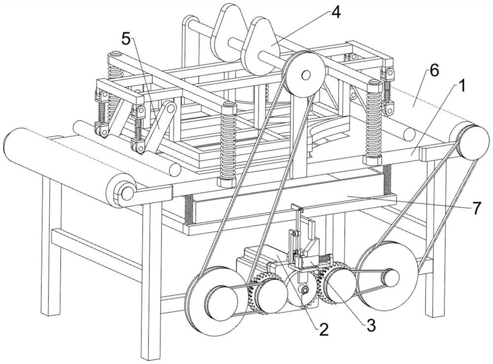
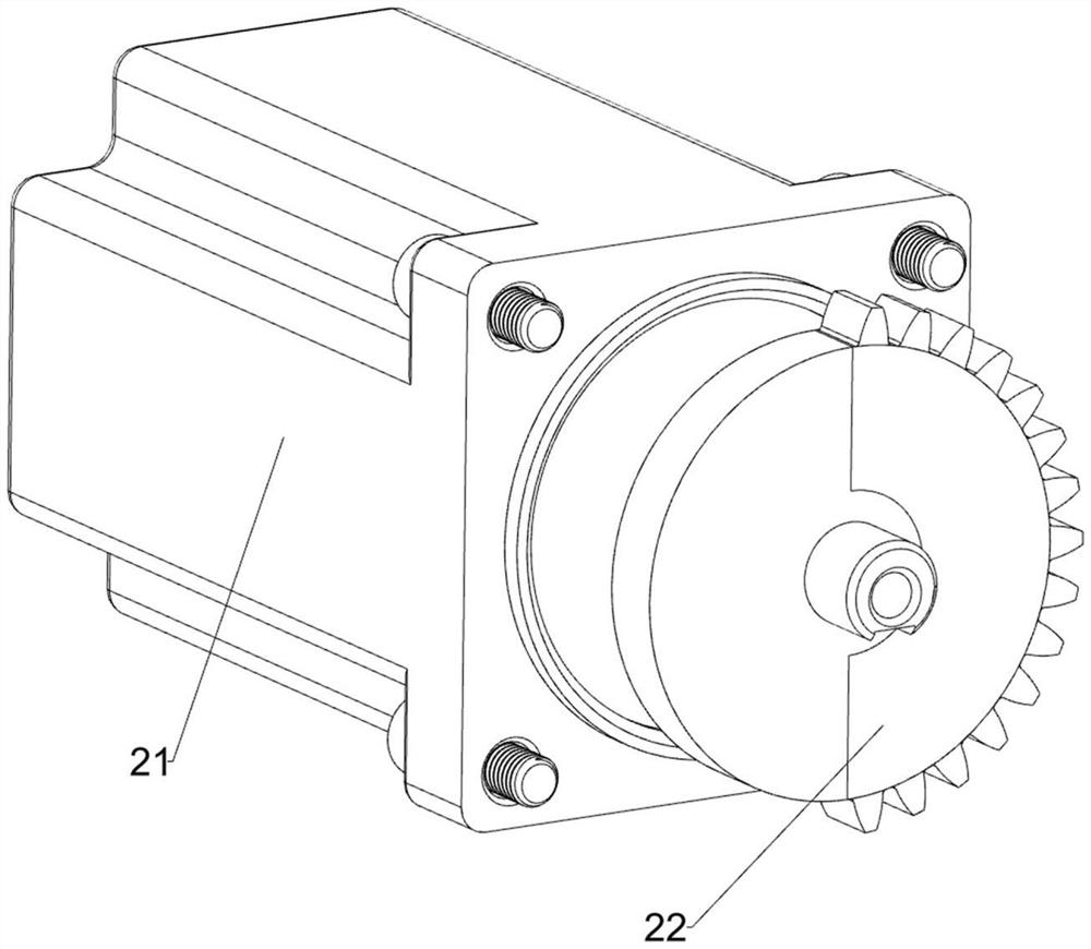
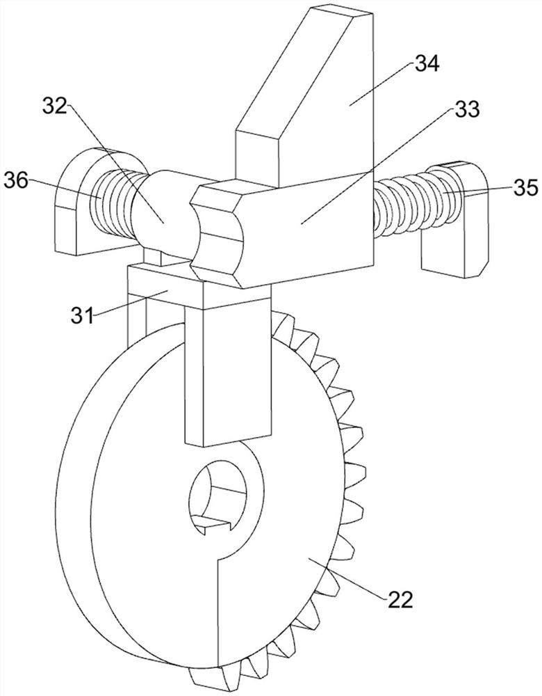
[0027] A cutting device for an apron, such as Figure 1-Figure 4 As shown, it includes a bracket 1, a power component 2, a control component 3 and a cutting component 4. The power component 2 powered by a motor is installed in the front middle of the bracket 1, and the upper middle of the front side of the bracket 1 is installed by sliding. The control assembly 3 of the control is provided with a cutting assembly 4 that cuts the cloth by sliding between the front side and the top of the support 1 .

[0028] When it is necessary to use the device to cut the apron fabric, the fabric is first placed on the top of the support 1, and then the power component 2 is controlled to start working, and the power component 2 drives the cutting component 4 to cut the fabric. In the process of cutting the fabric, workers are required Fix the fabric, after the piece of fabric is cut, disconnect the cutting component 4 from the power component 2 through the control component 3, then re-place t...

Embodiment 2

[0036] On the basis of Example 1, such as figure 1 , Figure 5 , Figure 6 and Figure 7 As shown, it also includes a compression assembly 5, and the left and right sides of the sliding frame 41 are equipped with a compression assembly 5. The compression assembly 5 includes a pole 51, a telescopic rod 52, a swing rod 53, a second concave block 54, Pressing roller 55 and the 4th spring 56, sliding frame 41 left and right sides all are welded with support rod 51, and the support rod 51 outer sides of left and right sides are all rotationally provided with telescopic rod 52, and telescopic rod 52 bottom ends are all welded with The second concave block 54, the fourth spring 56 is connected between the second concave block 54 and the top of the telescopic rod 52, and a fork 53 is provided in a rotating manner between the bottom of the second concave block 54 and the pole 51. All rotation type is provided with pressure roller 55 between the fork 53 bottom ends of the right side ...


PUM


Abstract

The invention relates to a cutting device, and in particular relates to a cutting device for aprons. The invention aims to provide the cutting device for the aprons, which can be used for quickly cutting cloth without damaging the cloth. The cutting device for aprons comprises a support; a power assembly, mounted on the bracket and powered by a motor to work; a control assembly, installed on the support and conducting control in a sliding mode; and a cutting assembly, installed on the support and used for cutting the cloth in a sliding mode. Through cooperation of the power assembly, the control assembly and the cutting assembly, the effect of rapidly cutting the cloth needed for manufacturing the apron is achieved; by means of a pressing assembly, when the cloth is cut, the cloth can be automatically fixed, the cloth cutting quality is improved, and meanwhile the device is safer to use; and by means of a waste winding assembly, the cut cloth can be automatically wound, and the deviceis more convenient to use.

Description

technical field [0001] The invention relates to a cutting device, in particular to a cutting device for an apron. Background technique [0002] The apron is used to block some unclean things from making the clothes dirty when cooking. It is called "help list" in Tibetan. When making an apron, the fabric needs to be cut. [0003] At present, when cutting the cloth for making an apron, you first need to use a pen to slide out the cut shape on the surface of the cloth, and then use scissors to cut the cloth. Although this method can cut the cloth for making an apron, it requires a lot of work. Be careful, otherwise it is easy to damage the fabric, and this cutting method is very slow. [0004] How to design a cutting device for an apron that can quickly cut the cloth without damaging the cloth has become a problem to be solved at present Contents of the invention [0005] In order to overcome the shortcomings of the current apron cloth cutting method that needs to be cauti...

Claims


Application Information

Patent Timeline
Patent Type & Authority Applications(China)
IPC IPC(8): D06H7/00
CPCD06H7/00
Inventor 赖正峰
Owner 江西诺捷科技股份有限公司
Why Eureka
Try Eureka