A measuring device and measuring method for simultaneous excitation of two components in a combustion field

A technology of synchronizing excitation and measurement devices, applied in measurement devices, material excitation analysis, scattering characteristic measurement, etc., can solve the difficult to meet the high dynamic change of combustion flow field diagnosis requirements, the detection timing cannot be completely synchronized, and it is impossible to achieve detection. Complete timing synchronization and other issues

Active Publication Date: 2021-07-06
HARBIN INST OF TECH
View PDF0 Cites 0 Cited by
  • Summary
  • Abstract
  • Description
  • Claims
  • Application Information

AI Technical Summary

Problems solved by technology

[0004] The traditional multi-component measurement is mainly based on the low frequency of 10Hz, and is limited by the fluorescence interference between adjacent bands. The detection timing cannot be completely synchronized (about a hundred nanoseconds of delay), and it is difficult to meet the requirements of the highly dynamic combustion flow field. diagnostic needs
LIFBASE simulations and experiments have confirmed that under high-frequency excitation conditions, the fluorescence lines of the CH C-X band and the OH A-X band will overlap (the CH fluorescence band is around 314nm, and the OH group fluorescence band is around 313nm). Discrimination methods are difficult or almost impossible to achieve full synchronization of detection timing

Method used


Image

  • A measuring device and measuring method for simultaneous excitation of two components in a combustion field

Examples


specific Embodiment approach 1

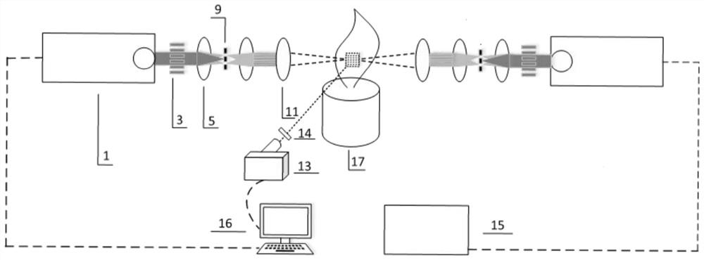
[0022] DETAILED DESCRIPTION OF THE INVENTION An a disclosure of which is disclosed a combustion field two-component synchronous excitation, including focusing lens 11, an ICMOS camera 13, an interference filter 14, a pulse signal generator 15, a computer 16, a combustor 17, Two laser emitter 1 and two sets of beam modulation systems; the burner 17 is disposed in the middle of the two laser emitter 1, each of which is in the laser emission direction between the laser emitter 1 and the burner 17 There is a beam modulation system and a focus lens 11, each set of beam modulation systems and corresponding focus lens 11 are confocally disposed with the combustion field of the combustor 17; the ICMOS camera 13 is equipped with an interference filter 14. The interference filter 14 is provided with the combustion field of the combustor 17; the pulse signal generator 15 is transmitted to two laser emitter 1 signal transmission, the computer 16 signal transmission connection, pulse signal ge...

specific Embodiment approach 2

[0023] DETAILED DESCRIPTION OF THE INVENTION 2: The present embodiment is a further description of the specific embodiment, and the laser emitter 1 outputs a laser wavelength of 310 nm, exciting CX band of the CH group; another laser emitter 1 output wavelength is 283 nm Laser, exciting the OH group's AX band.

specific Embodiment approach 3

[0024] BEST MODE FOR CARRYING OUT THE INVENTION 3: The present embodiment is a further description of the specific embodiment 2, and the two laser emitter 1 has no offset.


PUM


Abstract

The invention relates to a measuring device and a measuring method for two-component synchronous excitation of a combustion field, which belong to the technical field of combustion component visualization. The burner is set in the middle of the two laser emitters. Between each laser emitter and the burner, a beam modulation system and a focus lens are arranged in sequence along the laser emission direction. Each set of beam modulation system and the corresponding focus lens are compatible with the burner The confocal setting of the combustion field of the burner; the ICMOS camera is equipped with an interference filter, which is set in conjunction with the combustion field of the burner; the pulse signal generator is connected to the two laser transmitters for signal transmission, and the computer and the ICMOS camera Signal transmission connection. The non-contact measurement of the present invention does not interfere with the flame structure, overcomes the problem of overlapping fluorescent spectral lines of CH groups and OH groups under high-frequency excitation conditions, can achieve complete synchronization in timing, is simple in device, saves cost, and provides a Flame structure and pyrolysis data for combustion instability mechanism analysis and prediction.

Description

Technical field [0001] The present invention relates to a measuring device and a measurement method of bimetimetric synchronous excitation, belonging to the visualization of combustion components. Background technique [0002] Combustion instability refers to one of the long-established and important research topics in the field of combustion, the combustion oscillation in the combustion chamber audio or near the combustion chamber. In many studies in combustion instability, a single set of characterized flame kinetic information is not comprehensive and is not sufficient to explain the production and development mechanism of combustion instability. The intermediate component CH group and OH group in the combustion field are present in the combustion reaction zone and the high temperature zone, respectively, have been used as a tracer group that characterizes thermal release characteristics and flame structure. However, due to the lack of thermal release and flame structure data ...

Claims


Application Information

Patent Timeline
Patent Type & Authority Patents(China)
IPC IPC(8): G01N21/64G01N21/47G01N21/45
CPCG01N21/45G01N21/4788G01N21/6402G01N21/6456G01N2021/6463G01N2021/6471G01N2021/6495
Inventor 彭江波曹振于杨马欲飞赵永蓬常光高龙武国华韩明宏袁勋
Owner HARBIN INST OF TECH
Why Eureka
Try Eureka