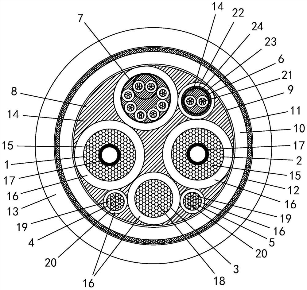
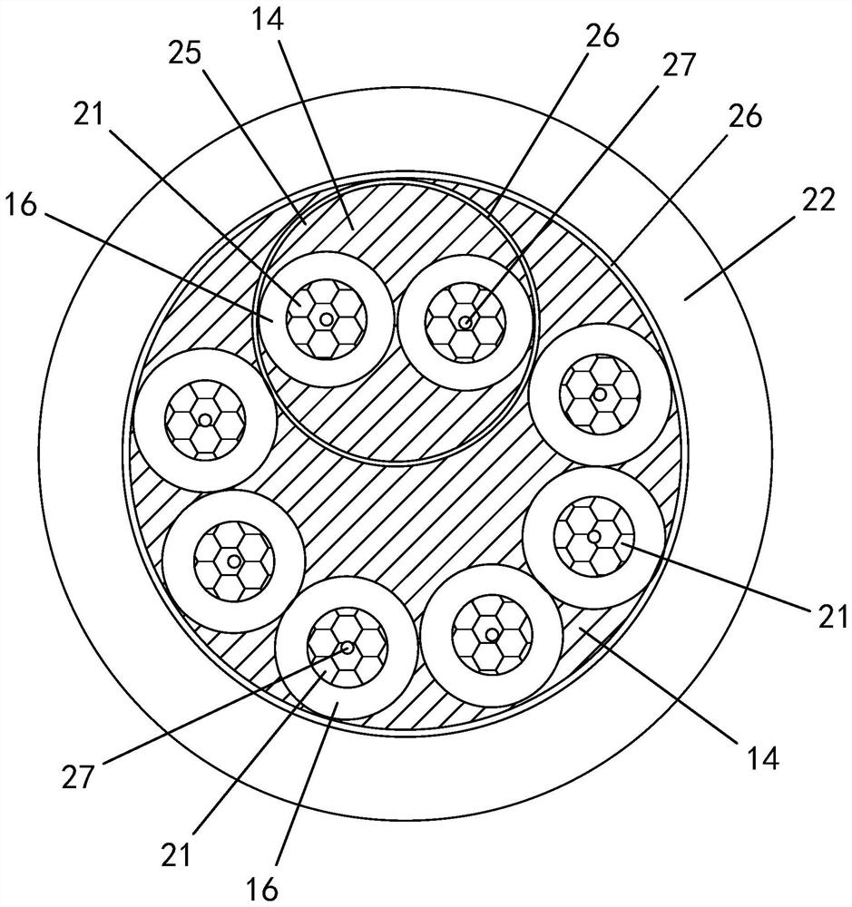
Charging cable for light high-current-carrying tensile anti-torsion liquid-cooling direct-current charging pile

A DC charging pile and charging cable technology, which is applied in charging stations, insulated cables, electric vehicle charging technology, etc., can solve the problems of damage to the internal signal core wire, auxiliary power core wire, increased cable weight, and high operator cost. Solve the problem of charging convenience and use safety, reduce weight, and improve the effect of operation management performance

Pending Publication Date: 2021-01-22
JIANGSU HENGTONG ELECTRONICS CABLE TECH CO LTD
View PDF0 Cites 3 Cited by
  • Summary
  • Abstract
  • Description
  • Claims
  • Application Information

AI Technical Summary

Problems solved by technology

Excessively large copper cores can achieve high power output, but at the same time greatly increase the weight of the cable, making it difficult to hold and drag during use, which greatly reduces the owner's desire to use the pile.
In addition, the unavoidable drag phenomenon can easily cause damage to the internal signal core wires and small-sized auxiliary power core wires during long-term use, resulting in frequent maintenance and replacement, causing excessive cost pressure on the operator

Method used


Image

  • Charging cable for light high-current-carrying tensile anti-torsion liquid-cooling direct-current charging pile
  • Charging cable for light high-current-carrying tensile anti-torsion liquid-cooling direct-current charging pile
  • Charging cable for light high-current-carrying tensile anti-torsion liquid-cooling direct-current charging pile

Examples


Embodiment

[0031] Embodiment: The following will clearly illustrate this case with drawings and detailed descriptions. After any person skilled in the art understands the embodiment of this case, he can change and modify it by the technology taught in this case without departing from the spirit of this case. with range.

[0032] The terminology used herein is for the purpose of describing particular embodiments only, and is not intended to be limiting of the present case. Singular forms such as "a", "the", "the", "this" and "the", as used herein, also include plural forms.

[0033] The terms “first” and “second” used herein do not refer to a sequence or order, nor are they used to limit the present application, but are only used to distinguish components or operations described with the same technical terms.

[0034] As used herein, "connection" or "positioning" can mean that two or more components or devices are in direct physical contact with each other, or that they are in indirect p...


PUM

PropertyMeasurementUnit
Specificationaaaaaaaaaa
Inner diameteraaaaaaaaaa
Wall thicknessaaaaaaaaaa

Abstract

The invention discloses a charging cable for a light high-current-carrying tensile anti-torsion liquid-cooling direct-current charging pile. The charging cable comprises an assembly cable, a first outer wrapping layer, an inner protective layer, a first braided shielding layer, a second outer wrapping layer and an outer protective layer from inside to outside, the assembly cable comprises an anodemain power line, a cathode main power line, a ground wire, an anode auxiliary power line, a cathode auxiliary power line, a double-shielding communication signal line group and a combination line. The main power line comprises a first central conductor and an insulating layer. The first central conductor is a copper-clad aluminum conductor which surrounds a cooling hose and is formed through crossed irregular twisting. The ground wire comprises a second central conductor and an insulating layer, and the second central conductor is a copper-clad aluminum conductor formed by crossed regular orirregular stranding; the auxiliary power line comprises a third central conductor and an insulating layer; the combination line is a combined stranded line of a plurality of signal lines and an unshielded communication signal line group; and the unshielded communication signal line group is formed by twisting two signal lines. The requirement for direct-current quick charging is met, and the situation that internal thin core wires are broken due to frequent dragging can be prevented.

Description

technical field [0001] The invention relates to the technical field of cables, in particular to a lightweight, high-current-carrying, tensile, and torsion-resistant charging cable for a liquid-cooled DC charging pile. Background technique [0002] The problem of the charging speed of new energy vehicles has become a major obstacle to the promotion. At present, the fast charging pile cables on the market mainly increase the charging power by expanding the cross-sectional area of ​​the copper conductor. Excessively large copper cores can achieve high power output, but at the same time greatly increase the weight of the cable, making it difficult to hold and drag during use, which greatly reduces the owner's desire to use the pile. In addition, the unavoidable drag phenomenon can easily cause damage to internal signal core wires and small-sized auxiliary power core wires during long-term use, resulting in frequent repairs and replacements, causing excessive cost pressure on the...

Claims


Application Information

Patent Timeline
IPC IPC(8): H01B7/42H01B7/00H01B7/18B60L53/18
CPCB60L53/18H01B7/0009H01B7/0045H01B7/1825H01B7/423Y02T10/70Y02T10/7072Y02T90/14Y02T90/16
Inventor 朱国梁朱凤郭燕清
Owner JIANGSU HENGTONG ELECTRONICS CABLE TECH CO LTD
Why Eureka
Try Eureka