a limiting device

A technology of a limit device and a limit column, which is applied in the field of mechanical parts, can solve the problems of no protection measures, shorten the service life of the device, economic losses, etc., achieve a wide range of temperature adaptation, accelerate heat dissipation, and reduce economic losses. Effect

Active Publication Date: 2022-04-08
江西中船航海仪器有限公司
View PDF5 Cites 0 Cited by
  • Summary
  • Abstract
  • Description
  • Claims
  • Application Information

AI Technical Summary

Problems solved by technology

[0003] At present, the existing limit devices in China mostly use proximity switches, which generate limit signals by inductive proximity switches, and are mostly used in industrial control occasions. The advantages are simple circuits and low cost. The disadvantage is that the limit method is single. , no other protection
[0004] Moreover, when the equipment is in use, it will generate a certain amount of heat due to the operation of the equipment during the working process. If the heat remains inside the equipment and cannot be dissipated, it will cause heat inside the device and reduce the service life of the device, which may cause some internal parts to be damaged. Damage occurs, causing internal failure of the device, making the device unable to work normally, thus affecting the work progress, and also causing economic losses and increasing the user's economic expenditure
[0005] In the fixing method of this kind of device that is usually seen, it is usually fixed directly with bolts. If the device is used for a long time, the bolts may become loose due to long-term use. If the user does not check the equipment regularly, the bolts When the device is loose, the device cannot be firmly fixed on the base, which may cause the device to shake violently. If it is serious, the device will be separated directly, making the device scrapped and unable to continue to be used. It may also reach the user and cause personal injury.
[0006] During the use of mechanical devices, it is inevitable that some failures will occur and the device cannot stop running. At this time, the device needs to be inspected and repaired, but some devices are sealed and connected by bolts, which makes maintenance and inspection very troublesome. , you need to unscrew the bolts step by step to check the internal conditions of the equipment

Method used


Image

  • a limiting device
  • a limiting device
  • a limiting device

Examples


Embodiment Construction

[0032] The technical solutions in the embodiments of the present invention will be clearly and completely described below in conjunction with the accompanying drawings in the embodiments of the present invention. Obviously, the described embodiments are only some of the embodiments of the present invention, not all of them; based on The embodiments of the present invention and all other embodiments obtained by persons of ordinary skill in the art without making creative efforts belong to the protection scope of the present invention.

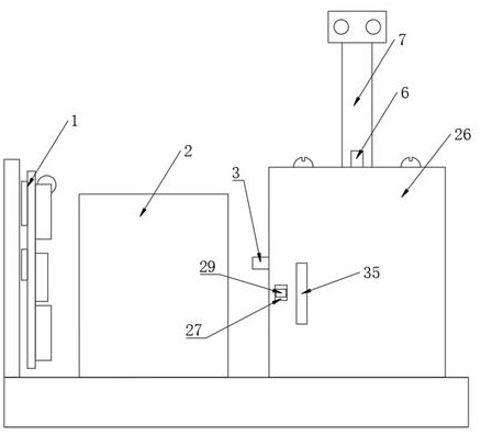
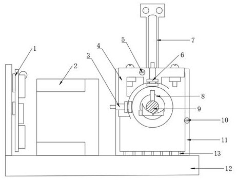
[0033] Depend on Figure 1-7Given, the present invention discloses a position limiting device, including a base 12, a stepper motor driver 1 is installed on the top of the base 12, and a stepper motor 2 is fixedly installed on one side of the stepper motor driver 1, so The side of the stepper motor 2 away from the stepper motor driver 1 is fixedly equipped with a speed reducer 11, and the middle position of the side surface of the speed reducer ...


PUM


Abstract

The invention discloses a new type of limit device, which uses a non-contact proximity switch as an electrical limit, which has higher precision than the contact limit method and is not affected by the number of times of use; it adopts three-level limit protection, namely: electrical Limit, software limit, mechanical limit, its priority is from high to low, under normal circumstances, the electrical limit will act first; the limit position is adjustable, and the positive limit and negative limit can be adjusted according to the actual situation; the positive limit After the position of the position and negative limit is determined, set the software limit according to the number of pulses required by the stepper motor to run a complete limit interval, which is flexible and convenient to set; it can also facilitate the heat dissipation inside the device when the device is running, and can reduce the Small vibration, reduce the noise generated during work.

Description

technical field [0001] The invention belongs to the technical field of mechanical parts, in particular to a position limiting device. Background technique [0002] The limit device refers to the part that ensures that the torsion angle of the elastic component does not exceed a certain limit value. The limit switch (hard limit) is the position limit of each axis on the electrical hardware, usually similar to the travel switch, and the mechanical limit is the mechanical limit. The position is limited, and rubber blocks are usually used to prevent hard impacts. [0003] At present, the existing limit devices in China mostly use proximity switches, which generate limit signals by inductive proximity switches, and are mostly used in industrial control occasions. The advantages are simple circuits and low cost. The disadvantage is that the limit method is single. , no other protective measures. [0004] Moreover, when the equipment is in use, it will generate a certain amount o...

Claims


Application Information

Patent Timeline
Patent Type & Authority Patents(China)
IPC IPC(8): H02P8/24H02P8/36H02K7/10H02K11/21H02K5/24F16H57/025F16H57/028F16H57/031F16H57/04
CPCH02P8/24H02P8/36H02K7/10H02K11/21H02K5/24F16H57/025F16H57/028F16H57/031F16H57/0416F16H2057/02034F16H2057/0081
Inventor 倪晓宇何鹏刘威
Owner 江西中船航海仪器有限公司
Why Eureka
Try Eureka