Relay

A relay, electromagnetic technology, applied in the direction of relay, electromagnetic relay, electromagnetic relay detailed information, etc., can solve the problem of increasing the installation space of the yoke-armature device

Pending Publication Date: 2021-01-22
PHOENIX CONTACT GMBH & CO KG
View PDF23 Cites 0 Cited by
  • Summary
  • Abstract
  • Description
  • Claims
  • Application Information

AI Technical Summary

Problems solved by technology

In order to achieve the fastening of the return spring, the return spring fastener can be arranged on the armature and/or...

Method used


Image

  • Relay
  • Relay
  • Relay

Examples


Embodiment Construction

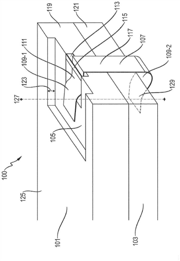
[0098] figure 1 A schematic diagram of the relay 100 , the relay includes an armature 101 and a yoke 103 that can be electromagnetically connected to the armature 101 . The armature 101 is at least partially flat on the yoke 103 , and the receiving groove 105 is partially formed in the armature 101 . The relay 100 also includes an arched clamping spring 107 , which is enclosed at the end faces of the armature 101 and the magnetic yoke 103 to fix the armature 101 on the magnetic yoke 103 . The arched clamping spring 107 has a first clamping arm 109 - 1 disposed in the receiving groove 105 and a second clamping arm 109 - 2 placed on the magnetic yoke 103 . Furthermore, the first clamp arm 109 - 1 has a curved tongue 111 which elastically engages in a recess 113 formed in the receiving groove 105 of the armature 101 .

[0099] The armature 101 has a web 115 which at least partially bridges the recess 113 and / or ends flush with the receiving groove 105 . The web 115 forms a c...


PUM


Abstract

The invention relates to a relay (100), comprising an armature (101) and a yoke (103) which can be electromagnetically coupled to the armature (101). The armature (101) lies flat at least partly on the yoke (103), and a receiving depression (105) is partly formed in the armature (101). The relay also comprises a bracket-shaped clamping spring (107) which surrounds the armature (101) and the yoke (103) on the end face in order to fix the armature (101) on the yoke (103). The bracket-shaped clamping spring (107) has a first clamping limb (109-1), which is arranged in the receiving depression (105), and a second clamping limb (109-2), which lies on the yoke (103). The first clamping limb (109-1) has an angled tab (111) which engages elastically into a recess (113) formed in the receiving depression (105) of the armature (101).

Description

technical field [0001] The present invention relates to a relay having a reduced overall depth for use in a junction box, in particular having a connection width of less than or equal to 3.5 mm. Background technique [0002] Electromagnetic switches, especially relays, generally have mechanical switching contacts that can be opened and closed by means of electromagnets. The mechanical switch usually has to apply a preset force to open and close. For this purpose, the mechanical switch can be connected to an armature, which usually has a high magnetic permeability. The armature can be connected to the electromagnet by means of a spring, so that when current flows through the electromagnet, the armature is deflected by the electromagnet, and when the current is disconnected, the armature is pressed into the original load position by the return spring. [0003] Since the magnetic field produced by the yoke can be proportional to the size of the yoke, and the magnetic force be...

Claims


Application Information

Patent Timeline
IPC IPC(8): H01H50/04H01H50/36
CPCH01H50/041H01H50/042H01H50/36H01H2050/044H01H2050/046H01H2050/367H01H50/043H01H50/18
Inventor 拉尔夫·霍夫曼
Owner PHOENIX CONTACT GMBH & CO KG
Why Eureka
Try Eureka