Automatic punching device for breeding nursing bed

A technology of punching device and nursery bed, which is applied in the direction of metal processing, etc., can solve the problems of low work efficiency and manpower consumption, and achieve the effects of improving work efficiency, simple operation and saving manpower

Pending Publication Date: 2021-01-26
龙锦明
View PDF8 Cites 2 Cited by
  • Summary
  • Abstract
  • Description
  • Claims
  • Application Information

AI Technical Summary

Problems solved by technology

[0003] At present, the method of punching the nursery bed board is usually to place the nursery bed board manually. The method can only push out one remaining material at a time during operation, the work efficiency is low, and it is more labor-intensive during operation

Method used


Image

  • Automatic punching device for breeding nursing bed
  • Automatic punching device for breeding nursing bed
  • Automatic punching device for breeding nursing bed

Examples


Embodiment 1

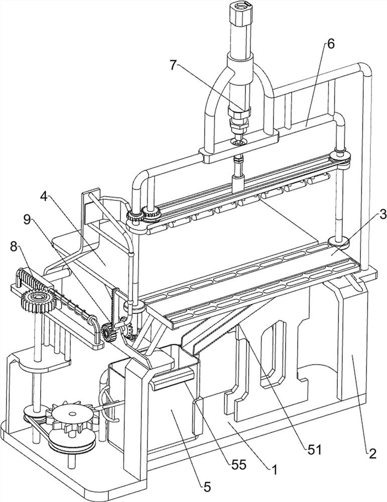
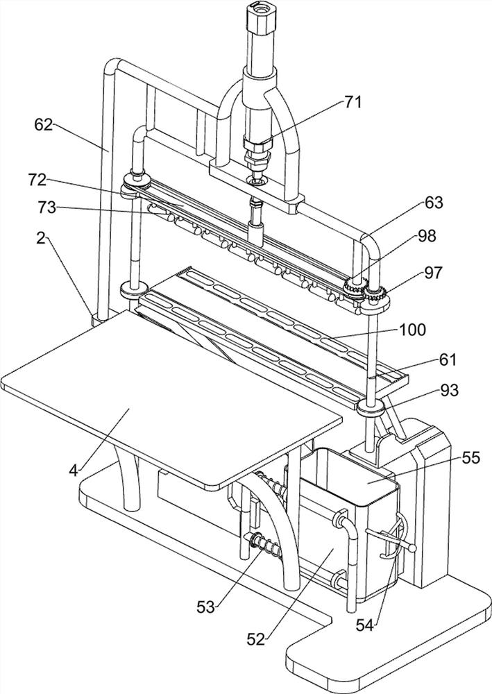
[0024] An automatic punching device for nursery beds for breeding, such as figure 1 and figure 2 As shown, it includes a base 1, a fixed plate 2, a placement frame 3 and a placement plate 4, the left and right sides of the top of the base 1 are connected with the fixed plate 2, the tops of the fixed plates 2 on both sides are connected with the placement frame 3, and the top of the base 1 The rear side is connected with a placement board 4, the top of the placement board 4 is slightly lower than the placement frame 3, the placement board 4 is located at the rear side of the placement frame 3, and also includes a receiving assembly 5, an installation assembly 6 and an opening assembly 7, and the base 1 is provided with There is a receiving assembly 5, and the fixing plate 2 is provided with an installation assembly 6, and the installation assembly 6 is provided with an opening assembly 7.

[0025] The material receiving assembly 5 includes a material receiving inclined frame ...

Embodiment 2

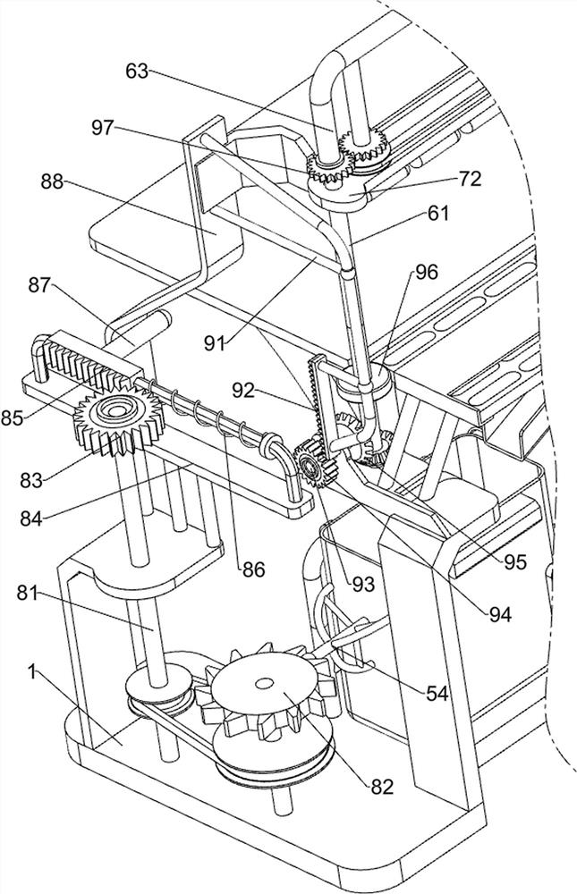
[0030] On the basis of Example 1, such as image 3 As shown, an extrusion assembly 8 is also included, and the extrusion assembly 8 includes a first rotating shaft 81, a ratchet gear 82, a first one-way gear 83, a guide frame 84, a driving rack 85, a return spring 86, a connecting rod 87 and Squeeze plate 88, the top left side of base 1 is rotatably connected with first rotating shaft 81, the left front side of base 1 top is rotatably connected with ratchet gear 82, and ratchet gear 82 cooperates with grip frame 54, and ratchet gear 82 is connected with first rotating shaft 81 Transmission connection, the top of the first rotating shaft 81 is connected with the first one-way gear 83, the left side of the top of the base 1 is connected with the guide frame 84, the guide frame 84 is rotatably matched with the first rotating shaft 81, and the driving rack is slidably connected to the guide frame 84 85, a return spring 86 is connected between the driving rack 85 and the guide fram...

Embodiment 3

[0033] On the basis of Example 2, such as figure 2 and image 3 As shown, a rotating assembly 9 is also included, and the rotating assembly 9 includes a connecting frame 91, a spur rack 92, a second rotating shaft 93, a second one-way gear 94, a bevel gear 95, a rubber wheel 96, a first transmission gear 97 and The second transmission gear 98, the extruding plate 88 is connected with a connecting frame 91, the connecting frame 91 is connected with a spur rack 92, the left fixed plate 2 is connected with a second rotating shaft 93 in a rotating manner, and the second rotating shaft 93 is connected with a The second one-way gear 94, the spur rack 92 will mesh with the second one-way gear 94, the second rotating shaft 93 and the left shaft rod 61 are connected with a bevel gear 95, and the two bevel gears 95 are meshed with each other, and the two shafts The lower part of the bar 61 is connected with rubber wheels 96, and the two rubber wheels 96 are respectively located on bot...


PUM


Abstract

The invention relates to a punching device, in particular to an automatic punching device for a breeding nursing bed. The device aims to solve the technical problem of how to design a automatic punching device of a nursing bed for breeding, and the device can push out more excess materials at a time, which improves the working efficiency and saves manpower. In order to solve the technical problem,the invention provides the automatic punching device for the breeding nursing bed. The device comprises a base, a placing frame, a placing plate and a material receiving assembly; fixing plates are connected with the two sides of the top of the base; the placing frame is connected between the tops of the fixing plates at the two sides; the placing plate is connected with the top of the base, andthe top of the placing plate is slightly lower than the placing frame; and the material receiving assembly is arranged on the base. According to the automatic punching device for the breeding nursingbed, the material collecting assembly, a mounting assembly and a punching assembly are matched to punch a breeding nursing bed plate, so that the effect of punching the breeding nursing bed plate is achieved.

Description

technical field [0001] The invention relates to a punching device, in particular to an automatic punching device for a breeding nursery bed. Background technique [0002] With the continuous development of modern society and the continuous improvement of people's living standards, in modern society, many people like to eat pork, so many places will set up pig farms. Farms usually use nursery beds when raising pigs. The nursery bed is a kind of pig raising equipment in modern society. During the production process of the nursery bed, it is usually necessary to cut out the shape on the nursery bed board, and then push out the remaining material to punch holes. [0003] At present, the method of punching the nursery bed board is usually to place the nursery bed board manually. The method can only push out one remaining material at a time during operation, the work efficiency is low, and it is more labor-intensive during operation. [0004] Therefore, need to research and deve...

Claims


Application Information

Patent Timeline
Patent Type & Authority Applications(China)
IPC IPC(8): B26F1/14B26D7/18
CPCB26D7/18B26F1/14
Inventor 不公告发明人
Owner 龙锦明
Why Eureka
Try Eureka