Working method for pipe fitting translation conveying mechanism

A transmission mechanism and working method technology, applied in the direction of conveyors, conveyor objects, transportation and packaging, etc., can solve the problems of smooth and uniform feeding of difficult pipes, falling of difficult pipes one by one, and failure of pipes, etc., so as to improve the degree of automation and structure well-designed effects

Inactive Publication Date: 2021-01-26
章凌霞
View PDF0 Cites 10 Cited by
  • Summary
  • Abstract
  • Description
  • Claims
  • Application Information

AI Technical Summary

Problems solved by technology

During the production and processing of pipe fittings, it is necessary to sequentially load the pipe fittings that have been processed in the previous process to enable the processing of the subsequent process. After the existing pipe fittings have been processed in the previous process, in order to continue to process the pipe Production and processing, the existing method is to manually feed the pipe fittings one by one, the labor intensity of the workers is high, and the feeding efficiency of the pipe fittings is low, making it difficult to meet the needs of large-scale pipe fitting production and processing. It is difficult for the feeding mechanism to realize the continuous, stable and uniform feeding of the pipe fittings one by one during the feeding process of the pipe fittings. The pipe fittings are stacked together vertically, making it difficult to drop the pipe fittings one by one, and it is difficult for the existing pipe fitting feeding drive mechanism to efficiently and accurately drive the support for pushing the pipe fittings to perform intermittent and smooth translational movements in the horizontal direction, making it difficult to ensure that the pipe fittings move along the horizontal direction. The direction is sequentially pushed and loaded intermittently, which affects the efficiency and quality of the normal processing of pipe fittings. The existing pipe fitting feeding equipment is difficult to adjust the processing position of the pipe fittings during the transmission process in the process of transferring the pipe fittings in sequence. The existing pipe fitting workers The position adjustment is mainly to use the manipulator to grab and adjust the pipe fittings, but the use of the manipulator to adjust the position requires first grabbing the pipe fittings. The existing manipulators often grab the pipe fittings in the process of In the process, the pipe fittings fall off due to poor grasping, resulting in the pipe fittings not being able to be processed normally in the subsequent process, so that the efficiency and quality of pipe fitting processing cannot be guaranteed, and in the process of using the manipulator to grab the pipe fittings, the manipulator needs to Multiple driving mechanisms are driven continuously and independently, the driving energy consumption is high, and the multi-driving mechanisms are also prone to failure, it is difficult to run stably for a long period of time, and it is impossible to ensure continuous and efficient grasping and placing of pipe fittings one by one to the required position. It is difficult to efficiently and accurately process the pipe fittings. The existing pipe fittings transfer mechanism is difficult to efficiently and smoothly rotate the pipe fittings during the falling process to adjust the station, which reduces the efficiency of pipe fittings transfer and processing. and quality, cannot meet the needs of processing and use

Method used


Image

  • Working method for pipe fitting translation conveying mechanism
  • Working method for pipe fitting translation conveying mechanism
  • Working method for pipe fitting translation conveying mechanism

Examples


Embodiment Construction

[0017] In order to further describe the present invention, a specific implementation of a pipe translation transmission mechanism will be further described below in conjunction with the accompanying drawings. The following examples are explanations of the present invention and the present invention is not limited to the following examples.

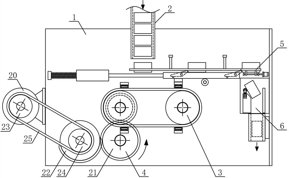
[0018] Such as figure 1 As shown, a pipe fitting translation transmission mechanism of the present invention includes a pipe transfer support 1, a drop pipe mechanism 2, a pipe push mechanism 3, a drive mechanism 4, a pipe transfer mechanism 5 and a conduit mechanism 6, and the pipe push mechanism 3 is horizontally arranged on the pipe transfer support 1- side, the drop tube mechanism 2 is vertically fixedly arranged on the tube transfer bracket 1 on the side above the tube push mechanism 3, the driving mechanism 4 is horizontally arranged on the tube transfer bracket 1 on the side below the tube push mechanism 3, and the tube transfer mech...


PUM


Abstract

The invention discloses a working method for a pipe fitting translation conveying mechanism and belongs to the field of workpiece conveying and machining mechanical equipment. According to the workingmethod for the pipe fitting translation conveying mechanism, a guide pipe material pipe is vertically and fixedly arranged on one side above a pipe moving support, translation armatures are arrangedon a plurality of armature sleeves fixedly arranged on the outer side of a pipe pushing belt, a plurality of pipe pushing rotating plates are arranged on a pipe pushing support at the end portion of atranslation guide rod in the horizontal direction, an adsorption electromagnet is arranged on one side below the pipe pushing support, guide pipe bearing rods are horizontally and symmetrically arranged on the two sides of the upper portion of the pipe pushing support respectively, a guide pipe inclined plate inclines downwards and is fixedly arranged on the part, on one side below a pipe movingmechanism, of the pipe moving support, and a conveying material pipe is vertically and fixedly arranged on the part, on the lower side of the guide pipe inclined plate, of the pipe moving support. Thepipe fitting translation conveying mechanism is reasonable in structural design, pipe fittings can be stably, accurately and sequentially pushed and fed in an intermittent translation mode in the horizontal direction and can be conveniently and smoothly rotated to adjust the conveying station, the automation degree of pipe fitting conveying and machining is improved, and the machining and using requirements are met.

Description

technical field [0001] The invention belongs to the field of workpiece conveying and processing machinery, and in particular relates to a working method of a translational conveying mechanism for pipe fittings, which is mainly applied to the continuous conveying and processing of pipe fittings. Background technique [0002] Pipe fittings refer to workpieces with a cylindrical structure. There are many types of pipe fittings. Different pipe fittings use different materials. The quality of the material directly determines the quality of the pipe fittings. Pipe fittings are necessary materials for construction engineering and mechanical equipment. A general term for components that play the roles of connection, control, direction change, flow diversion, sealing, support, etc. Steel pipe fittings are the most important type of pipe fittings. Steel pipe fittings are pressure-bearing pipe fittings. According to different processing techniques, steel pipe fittings can be divided in...

Claims


Application Information

Patent Timeline
Patent Type & Authority Applications(China)
IPC IPC(8): B65G47/08B65G47/84B65G47/28B65G47/88
CPCB65G47/08B65G47/28B65G47/844B65G47/8807B65G2201/0276
Inventor 章凌霞
Owner 章凌霞
Why Eureka
Try Eureka