Underwear dyeing and drying system

A drying system and underwear technology, applied in the direction of processing textile material carrier, processing textile material equipment configuration, textile material processing, etc. The effect of prolonging the service life

Inactive Publication Date: 2021-01-26
史彦龙
View PDF1 Cites 4 Cited by
  • Summary
  • Abstract
  • Description
  • Claims
  • Application Information

AI Technical Summary

Problems solved by technology

[0002] For example, the publication number CN207331269U includes a fixed seat, a first cloth guide roller is connected between the two first bearings, a second cloth guide roller is connected between the two second bearings, and the inner side of the first mounting ring is inserted with a rotating rod, the lower side of the inner wall of the first sleeve is movably connected with the second sleeve, the fourth cloth guide roller is connected be...

Method used


Image

  • Underwear dyeing and drying system
  • Underwear dyeing and drying system
  • Underwear dyeing and drying system

Examples


specific Embodiment approach 1

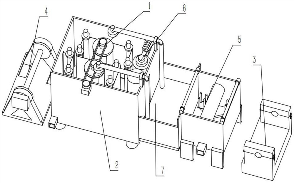
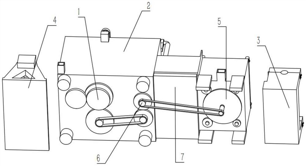
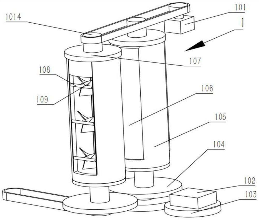
[0036] Combine below Figure 1-13Describe this embodiment, an underwear dyeing and drying system, including a drying mechanism 1 and a limit mechanism 2, the drying mechanism 1 includes a motor II 102, a gear 103, a gear shaft 104, a sleeve 105, a heating resistor 108, and a fan 109. The motor III 1012 and the sprocket shaft 1013 are provided with two gears 103, one of which is fixedly connected to the gear shaft 104, and the other gear 103 is fixedly connected to the output shaft of the motor II 102, and the two gears 103 are meshed for transmission. The gear shafts 104 are respectively fixedly connected to the bottom ends of the two sleeves 105, and the two gear shafts 104 are meshed for transmission. The two sleeves 105 are provided with multiple heating resistors 108, and the left and right ends of the multiple sprocket shafts 1013 are fixed. A fan 109 is connected, and multiple sprocket shafts 1013 are rotatably connected in the sleeve 105. The output shaft of the motor I...

specific Embodiment approach 2

[0039] Combine below Figure 1-13 Describe this embodiment, this embodiment will further explain the first embodiment, the drying mechanism 1 also includes a motor 101, a baffle 106, an end cover 107, a ratchet ring 1010, a tooth 1011, a sprocket 1014, two end covers 107 They are respectively rotatably connected to the two sleeves 105, two baffles 106 are fixedly connected to the two end caps 107, the ratchet ring 1010 is fixedly connected to the sleeve 105, and the two teeth 1011 are rotatably connected to the end caps 107. , the ratchet ring 1010 is engaged with the teeth for transmission, and the two end covers 107 and the output shaft of the motor 101 are fixedly connected with a sprocket 1014, and the three sprockets 1014 are driven by a chain;

[0040] The rotation of the sleeve 105 drives the ratchet ring 1010 to rotate, the tooth 1011 does not move when the ratchet ring 1010 rotates, the end cover 107 and the baffle plate 106 rotate with the sleeve 105, the rotation of...

specific Embodiment approach 3

[0042] Combine below Figure 1-13 Describe this embodiment, this embodiment will further explain the second embodiment, the limit mechanism 2 also includes a drying box 201, a drain 203 and a feeding hole 204, a plurality of rotating rods 202 are rotatably connected to the drying Inside the box 201, the drying box 201 is provided with two feeding holes 204, the drying box 201 is provided with a drain port 203, the two gear shafts 104 are connected to the drying box 201 in rotation, and the motor 101 is fixedly connected to the drying box 201. dry box 201;

[0043] The drain port 203 is used to discharge water and paint, and the feeding hole 204 is used for the entry and exit of cloth.


PUM


Abstract

The invention relates to the field of fabric drying, in particular to an underwear dyeing and drying system. The system comprises a drying mechanism and a limiting mechanism, wherein the drying mechanism comprises a motor II, gears, gear shafts, sleeves, heating resistors, fans, a motor III and chain wheel shafts; one gear is fixedly connected to the corresponding gear shaft, and the other gear isfixedly connected to an output shaft of the motor II; the two gears are in meshing transmission; the two gear shafts are fixedly connected to the bottom ends of the two sleeves respectively; the twogear shafts are in meshing transmission; the two sleeves are each provided with the plurality of heating resistors; the fans are fixedly connected to the left ends and the right ends of the multiple chain wheel shafts; the multiple chain wheel shafts are rotationally connected to the interiors of the sleeves; an output shaft of the motor III is in transmission connection with the multiple chain wheel shafts through chains; the motor III is fixedly connected to the interior of the corresponding sleeve; the limiting mechanism comprises rotating rods and limiting plates; and the upper ends and the lower ends of the multiple rotating rods are fixedly connected with the limiting plates.

Description

technical field [0001] The invention relates to the field of fabric drying, in particular to an underwear dyeing and drying system. Background technique [0002] For example, the publication number CN207331269U includes a fixed seat, a first cloth guide roller is connected between the two first bearings, a second cloth guide roller is connected between the two second bearings, and the inner side of the first mounting ring is inserted with a rotating rod, the lower side of the inner wall of the first sleeve is movably connected with the second sleeve, the fourth cloth guide roller is connected between the two fourth bearings, and the fifth cloth guide roller is connected between the two fifth bearings, The bottom of the inner chamber of the drying box is connected with a heater, the outer side of the spiral tube is provided with a cooling water tank, and the upper side of the top of the purification box is connected with an activated carbon layer; the disadvantage of this inv...

Claims


Application Information

Patent Timeline
IPC IPC(8): D06B3/10D06B19/00D06B23/04D06B23/20D06B15/00
CPCD06B3/10D06B15/00D06B19/0005D06B23/04D06B23/20D06B23/205
Inventor 史彦龙
Owner 史彦龙
Why Eureka
Try Eureka