Mixing pile drilling and coring structure and operation process

A technology of drilling coring and operation technology, which is applied in the direction of drill bits, drilling equipment, earthwork drilling and mining, etc., and can solve problems such as core sample erosion, detection accuracy impact, and core sample integrity, so as to maintain integrity and ensure The effect of detection accuracy

Active Publication Date: 2021-01-26
深圳华力岩土工程有限公司
View PDF13 Cites 0 Cited by
  • Summary
  • Abstract
  • Description
  • Claims
  • Application Information

AI Technical Summary

Problems solved by technology

[0004] In view of the above-mentioned related technologies, the inventor believes that the flushing liquid easily enters the inner tube during the coring process, thereby eroding the core sample and affecting the core sample. Integrity when taken out, defects that affect detection accuracy

Method used


Image

  • Mixing pile drilling and coring structure and operation process
  • Mixing pile drilling and coring structure and operation process
  • Mixing pile drilling and coring structure and operation process

Examples


Embodiment 1

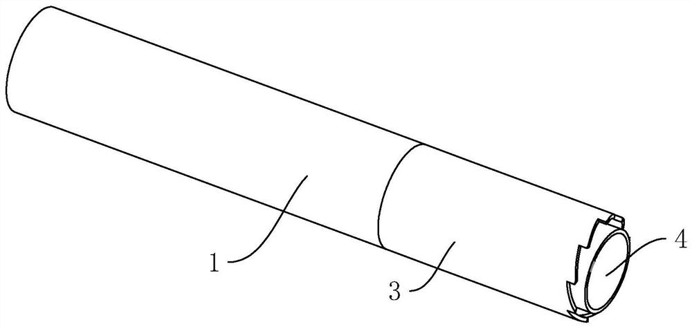
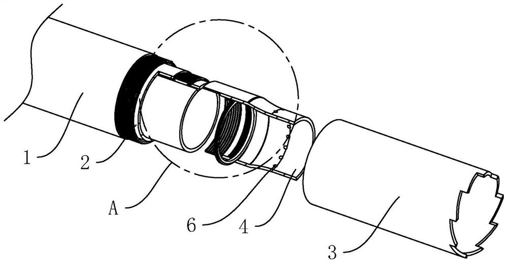
[0047] refer to figure 1 and figure 2 , the stirring pile drilling and coring structure includes a drill pipe body, the drill pipe body includes a cylindrical hollow outer tube 1 and an inner tube 2, wherein the inner tube 2 is located on the inner wall of the outer tube 1 and rotates with the outer tube 1 through a bearing, One end of the outer tube 1 is threaded with a hollow alloy drill bit 3 for drilling the pile body. The diameter of the outer peripheral surface of the alloy drill bit 3 is equal to the diameter of the outer peripheral surface of the outer tube 1 to ensure that the alloy drill bit 3 is installed After the outer tube 1, the flatness between the outer tube 1 and the outer tube 1.

[0048] refer to figure 2 and image 3 The end of the inner tube 2 close to the alloy drill bit 3 is threaded with a hollow guide nozzle 4, the diameter of the end of the guide nozzle 4 close to the inner tube 2 is larger than the diameter of the end of the guide nozzle 4 away...

Embodiment 2

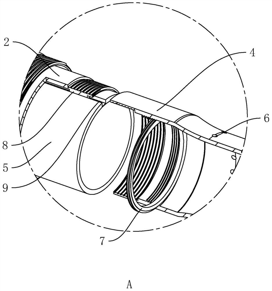
[0053] refer to Figure 4 and Figure 5 The difference between this embodiment and Embodiment 1 is that the guide nozzle 4 is connected and fixed to the inner tube 2 in a different way, wherein the inner tube 2 includes a tube body 201 and a socket fixedly connected to a point in the length direction of the tube body 201 202 , the end surface of the guide nozzle 4 facing the inner tube 2 is provided with an inserting groove 13 , and the inserting portion 202 is inserted and matched with the inserting groove 13 .

[0054] Continue to refer to Figure 4 and Figure 5 The pipe body 201 and the guide nozzle 4 have the same diameter near the free end of the pipe body 201, so as to keep the smoothness between the guide nozzle 4 and the inner pipe 2 after the guide nozzle 4 is installed on the inner pipe 2. Several bolts 10 are arranged on the guide nozzle 4, and the bolts 10 are wound around There are several evenly distributed around the axis of the guide nozzle 4, and the bolts...


PUM


Abstract

The invention relates to the technical field of mixing pile drilling and coring equipment, in particular to a mixing pile drilling and coring structure and operation process. The mixing pile drillingand coring structure comprises a drill rod body, the drill rod body comprises an outer pipe and an inner pipe, the inner pipe is located in the outer pipe and is in rotating fit with the outer pipe, and a hollow alloy drill bit is installed at one end of the outer pipe; a guide nozzle is installed at the end, close to the alloy drill bit, of the inner pipe, and a plurality of drainage holes are formed in the free end, away from the inner pipe, of the guide nozzle and distributed in the circumferential direction around the axis of the guide nozzle. The mixing pile drilling and coring structurehas the effects that flushing fluid is not prone to entering the inner pipe in the coring process, and the integrity of a core sample in the taking-out process and the detection precision of the pileforming quality are kept.

Description

technical field [0001] The present application relates to the field of drilling and coring equipment for stirring piles, in particular to a drilling and coring structure and operation process for stirring piles. Background technique [0002] Cement mixing pile refers to an effective form of soft foundation treatment. It is a main agent that uses cement as a curing agent. The cement is sprayed into the soil by a mixing pile machine and fully stirred to make a series of physical and chemical reactions between the cement and the soil. , to harden the soft soil and improve the strength of the foundation. [0003] The commonly used detection method for the pile quality of cement mixing piles is the drilling core detection method, which is mainly realized by drilling the drill pipe in the length direction of the mixing pile body by the drilling rig to obtain core samples. Single-action drilling tools are used for sampling, that is, during the coring process, the outer tube is con...

Claims


Application Information

Patent Timeline
Patent Type & Authority Applications(China)
IPC IPC(8): E21B25/10E21B21/00E21B10/02
CPCE21B25/10E21B21/00E21B10/02
Inventor 洪东生
Owner 深圳华力岩土工程有限公司
Why Eureka
Try Eureka