Combination switch for internal combustion engine-driven work machine

A technology of operating machinery and combined switches, which is applied in the direction of machine/engine, mechanical equipment, engine control, etc., can solve the problems of inconvenient maintenance and overhaul, increased damage to parts, and affecting the service life of combined switches, so as to simplify the structure and manufacture The effect of cost reduction

Pending Publication Date: 2021-01-26
CHONGQING ZONGSHEN GENERAL POWER MACHINE
View PDF1 Cites 0 Cited by
  • Summary
  • Abstract
  • Description
  • Claims
  • Application Information

AI Technical Summary

Problems solved by technology

[0007] Existing combination switches are mainly divided into two types: one type is the loose-piece type, and the components of this type of combination switch are respectively assembled on the switch mounting plate of the terminal product. When overhauling, it is necessary to dismantle some or all of the components of the combination switch, which not only brings inconvenience to maintenance, but also easily loses some small parts
Another form is to assemble the combination switch itself into an assembly, and then assemble it with the terminal, but this method is often more complicated in structure, not only the switch seat will be used to control the cable of the choke, the micro switch , fuel switch, gear structure, etc. are installed together, and a switch cover that cooperates with the switch seat needs to be provided to prevent the parts installed on the switch seat from being scattered during transportation. For example, the patent document with the publication number CN211038847U discloses " A combination switch for a variable frequency generator, the switch includes a switch base and a switch upper cover that cooperate with each other, and the feature is that a cam mechanism and a micro switch are arranged in a cavity surrounded by the switch base and the switch upper cover , a choke cable protruding from the switch base is provided on the cam mechanism, a switch handle and a fuel switch connected to the cam mechanism are respectively provided on the upper end surface of the switch upper cover and the lower end surface of the switch base, and the switch The handle is connected to the fuel switch through screws; the inner bottom of the switch base is provided with a "gear slideway" that cooperates with the cam mechanism. Due to the large number of parts, it increases the difficulty of assembly and processing of the combined switch, and also increases the The probability of component damage during frequent use will affect the service life of the combination switch, and the complex structure will also cause inconvenience to daily maintenance and repair

Method used


Image

  • Combination switch for internal combustion engine-driven work machine
  • Combination switch for internal combustion engine-driven work machine
  • Combination switch for internal combustion engine-driven work machine

Examples


Embodiment Construction

[0024] The following is further described in detail through specific implementation methods:

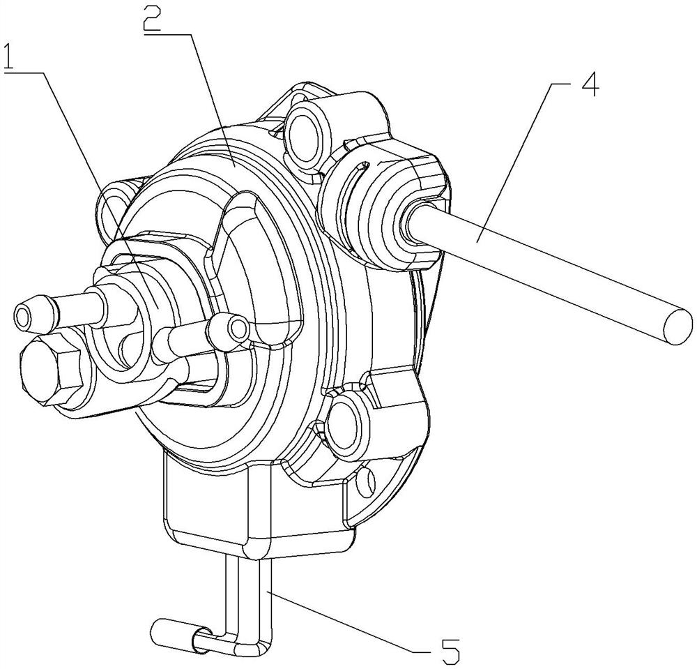
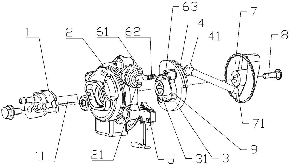
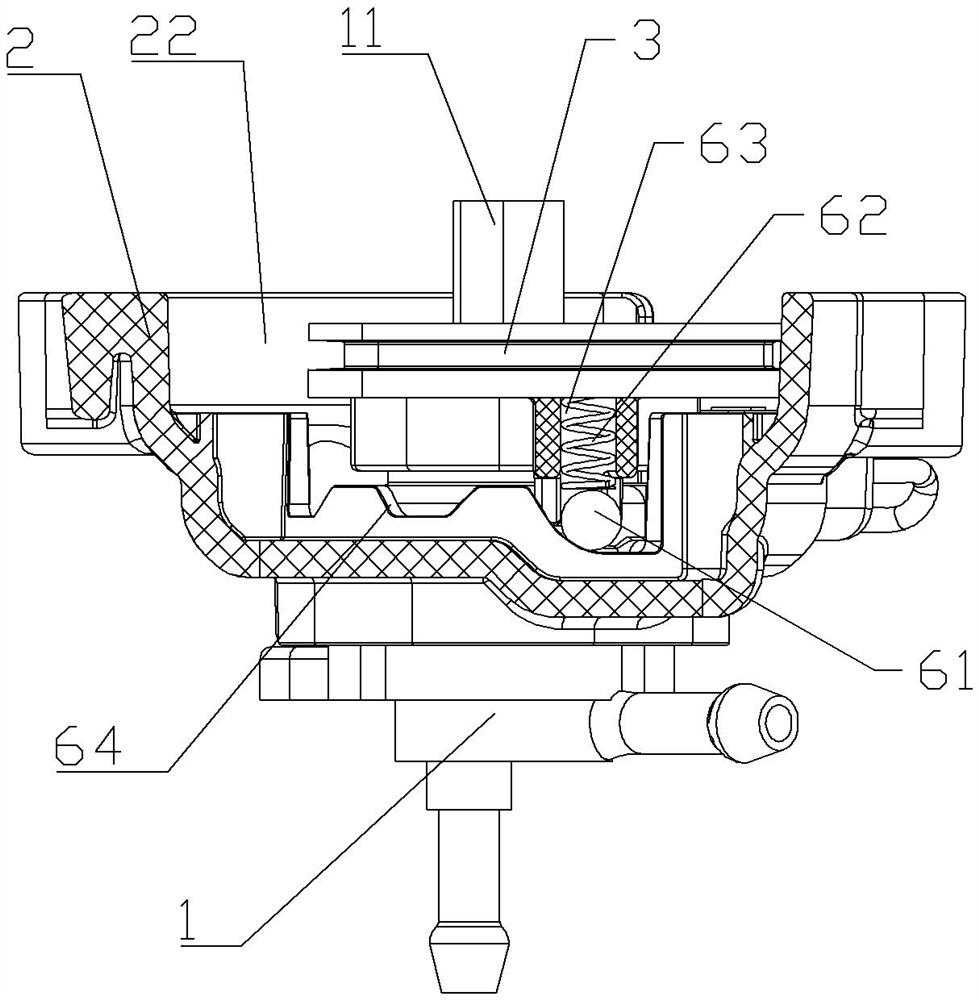
[0025] The reference signs in the drawings of the specification include: fuel switch 1, switch shaft 11, switch seat 2, card slot 21, accommodation chamber 22, cable shaft 3, connection hole 31, cable 4, bushing 41, micro switch 5. Steel ball 61, spring 62, steel ball limit hole 63, gear chute 64, switch handle 7, counterbore 71, screw 8, toggle piece 9.

[0026] The embodiment is basically as attached figure 1 , figure 2 , image 3 and Figure 4 Shown: a combination switch for an internal combustion engine-driven operating machine, including a switch base 2, a fuel switch 1, a cable 4, a cable shaft 3, a micro switch 5, a gear structure and a switch handle 7; the switch base 2 has an open The semi-enclosed structure of the mouth-type accommodation chamber 22, the fuel switch 1 is connected to the switch base 2 by bolts, the fuel switch 1 is provided with a switch shaft 11, and ...


PUM


Abstract

The invention belongs to the field of multifunctional non-electric combined control devices of internal combustion engines, and particularly relates to a combination switch for an internal combustionengine-driven work machine. The combination switch comprises a switch seat, a fuel switch, an inhaul cable, an inhaul cable rotating shaft, a gear structure and a switch handle; the fuel switch is connected with the switch seat, and the inhaul cable is sleeved with a sleeve; the fuel switch is provided with a non-cylindrical switch rotating shaft, a toggle piece in on-off fit with a microswitch controlling a flameout switch is arranged on the switch rotating shaft in a linkage mode, and the inhaul cable rotating shaft is provided with a non-cylindrical connecting hole matched with the switch rotating shaft; the end, away from the fuel switch, of the switch rotating shaft penetrates through the connecting hole and is statically connected with the switch handle, thus, the switch handle and the switch seat form a structure for surrounding the inhaul cable rotating shaft and the gear structure together; and the sleeve is clamped and fixed with the switch seat. According to the scheme, theproblems of complex structure and inconvenient maintenance of the combination switch in the prior art are solved.

Description

technical field [0001] The invention belongs to the field of non-electric combined control devices with multiple functions of an internal combustion engine, and specifically relates to a combination switch for an internal combustion engine-driven operating machine. Background technique [0002] Combination switch for internal combustion engine-driven operating machinery, including fuel switch, cable for controlling choke, micro switch for controlling flameout switch, gear position structure and switch handle for operation, which generally includes start gear, running gear And the stop gear, some will also set the relevant oil gear, the fuel switch, the cable and the micro switch can be operated at the same time through the switch handle, so as to achieve the purpose of reducing the user's operation steps; in different gears, its functions are roughly as follows: [0003] ①Starting gear: make the fuel switch in the open position, the choke valve in the closed position, and th...

Claims


Application Information

Patent Timeline
Patent Type & Authority Applications(China)
IPC IPC(8): F02D37/00
CPCF02D37/00
Inventor 万青源刘友忠
Owner CHONGQING ZONGSHEN GENERAL POWER MACHINE
Why Eureka
Try Eureka