
Rotor assembly of high-power brushless electronic water pump and mounting structure of rotor assembly

An electronic water pump and high-power technology, which is applied in the direction of pump devices, magnetic circuit shape/style/structure, parts of pumping devices for elastic fluids, etc., can solve the problem of small torque and the inability to increase the power of brushless electronic water pumps, etc. problem, to achieve the effect of strong magnetism and low production difficulty

Pending Publication Date: 2021-01-26
江苏朗信电气股份有限公司
View PDF1 Cites 0 Cited by
  • Summary
  • Abstract
  • Description
  • Claims
  • Application Information

AI Technical Summary

Problems solved by technology

[0003] 1. The rotor assembly includes an impeller and a connecting cylinder arranged at the bottom of the impeller. A wear-resistant lubricating insert is embedded concentrically in the inner hole of the connecting cylinder, and a wear-resistant lubricating insert is provided on the connecting cylinder. The center hole is set concentrically in the inner hole, the outer concentric sleeve of the connecting cylinder is fixed with the yoke cylinder, and the outer concentric sleeve of the yoke cylinder is fixed with the magnetic ring cylinder. This structure leads to the magnetic ring cylinder, the magnetic yoke cylinder and the wear-resistant lubrication The insert needs to be injection-molded as a whole, and the magnetic ring cylinder is also injection-molded NdFeB. The magnetism of this magnetic ring cylinder is relatively small, so the torque generated by the brushless electronic water pump is small due to the small magnetic force when the volume is limited. Relatively small, the power of the brushless electronic water pump cannot be increased

Method used


Image

  • Rotor assembly of high-power brushless electronic water pump and mounting structure of rotor assembly
  • Rotor assembly of high-power brushless electronic water pump and mounting structure of rotor assembly
  • Rotor assembly of high-power brushless electronic water pump and mounting structure of rotor assembly

Examples


Embodiment Construction

[0029] The present invention will be described in further detail below through specific examples.

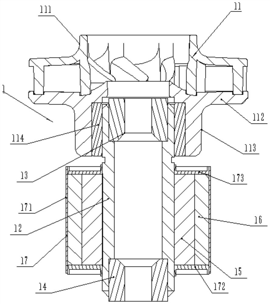
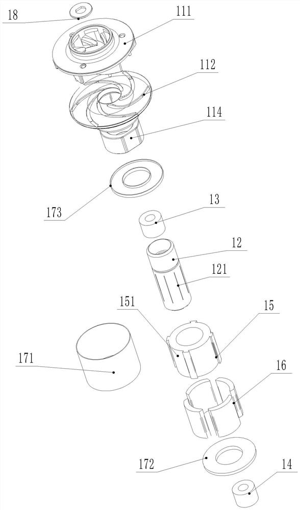
[0030] Such as figure 1 and figure 2As shown, a rotor assembly 1 of a high-power brushless electronic water pump includes an impeller 11 and a rotor sleeve 12, the impeller 11 is fixed on the upper end of the rotor sleeve 12, and the upper and lower ends of the rotor sleeve 12 are An upper wear-resistant lubricating insert 13 and a lower wear-resistant lubricating insert 14 are respectively concentrically embedded in the inner hole, and the upper wear-resistant lubricating insert 13 and the lower wear-resistant lubricating insert 14 are provided with an inner joint with the rotor bushing 12. The center hole of the hole concentric setting, the outer periphery of described rotor bushing 12 is fixed with rotor iron core 15, and the outer circumference of described rotor iron core 15 is evenly distributed with several pieces of sintered RuFeB magnetic steel 16, and described rotor...


PUM


Abstract

The invention discloses a rotor assembly of a high-power brushless electronic water pump and a mounting structure of the rotor assembly. The rotor assembly comprises an impeller and further comprisesa rotor shaft sleeve, wherein the impeller is fixed at the upper end part of the rotor shaft sleeve; an upper wear-resisting lubricating insert and a lower wear-resisting lubricating insert are concentrically embedded in inner holes at the upper end and the lower end of the rotor shaft sleeve respectively, and the upper wear-resisting lubricating insert and the lower wear-resisting lubricating insert are provided with center holes arranged being concentric with the inner holes of the rotor shaft sleeve; and a rotor iron core is fixed to the periphery of the rotor shaft sleeve, a great deal ofsintered Ru-Fe-B magnetic steel are evenly distributed on the periphery of the rotor iron core, and a rotor shell sleeve for wrapping and fixing the rotor iron core and the sintered Ru-Fe-B magnetic steel is fixed outside the rotor shaft sleeve. According to the rotor assembly, the magnetism of a rotor can be increased, the torque is increased, and then the power of the rotor assembly is improved.

Description

technical field [0001] The invention relates to a rotor assembly of a high-power brushless electronic water pump and its installation structure. Background technique [0002] The electronic water pump uses the magnetic interaction between the rotor and the stator to drive the impeller to rotate. The applicant applied for a brushless electronic water pump with the patent number 201720017208.3 in 2017. The rotor assembly of the brushless electronic water pump always rotates smoothly, with small rotation resistance and high water output efficiency. The electronic water pump has higher reliability and longer service life. long. However, the brushless electronic water pump still has the following disadvantages in actual use: [0003] 1. The rotor assembly includes an impeller and a connecting cylinder arranged at the bottom of the impeller. A wear-resistant lubricating insert is embedded concentrically in the inner hole of the connecting cylinder, and a wear-resistant lubricati...

Claims


Application Information

Patent Timeline
IPC IPC(8): F04D13/06F04D29/18F04D29/22F04D29/04F04D29/10F04D29/42F04D29/62F04D29/06H02K1/27H02K1/28
CPCF04D13/0606F04D13/0626F04D13/064F04D29/04F04D29/061F04D29/106F04D29/185F04D29/22F04D29/4293F04D29/628H02K1/27H02K1/28
Inventor 丁言闯赵行行赵浩东
Owner 江苏朗信电气股份有限公司
Learn More