
An automatic defrosting air-temperature vaporizer

An air temperature, vaporizer technology, applied in non-pressure vessels, vessel filling methods, vessel discharge methods, etc., can solve the problems of no defrosting function, increased energy consumption, hidden safety hazards, etc., to improve the vaporization effect, increase the Contact area, the effect of improving safety

Active Publication Date: 2022-02-01
苏州杜尔气体化工装备有限公司
View PDF5 Cites 0 Cited by
  • Summary
  • Abstract
  • Description
  • Claims
  • Application Information

AI Technical Summary

Problems solved by technology

[0003] 1. There is no defrosting function, resulting in frosting after the air-temperature vaporizer works for a period of time, which not only affects the vaporization efficiency of the subsequent low-temperature liquid, but also easily causes damage to components;
[0004] 2. Use the auxiliary heating device to defrost the air-temperature evaporator, which increases energy consumption, and due to changes in external temperature and wind speed, the pressure in the heat exchange tube fluctuates greatly, which poses a certain safety hazard;
[0005] 3. The low temperature liquid is only heat exchanged through the heat exchange tube. As the operation time goes by, the vaporization effect of the low temperature liquid shows a downward trend, so that the low temperature liquid in the heat exchange tube cannot be completely evaporated.

Method used


Image

  • An automatic defrosting air-temperature vaporizer
  • An automatic defrosting air-temperature vaporizer
  • An automatic defrosting air-temperature vaporizer

Examples


Embodiment Construction

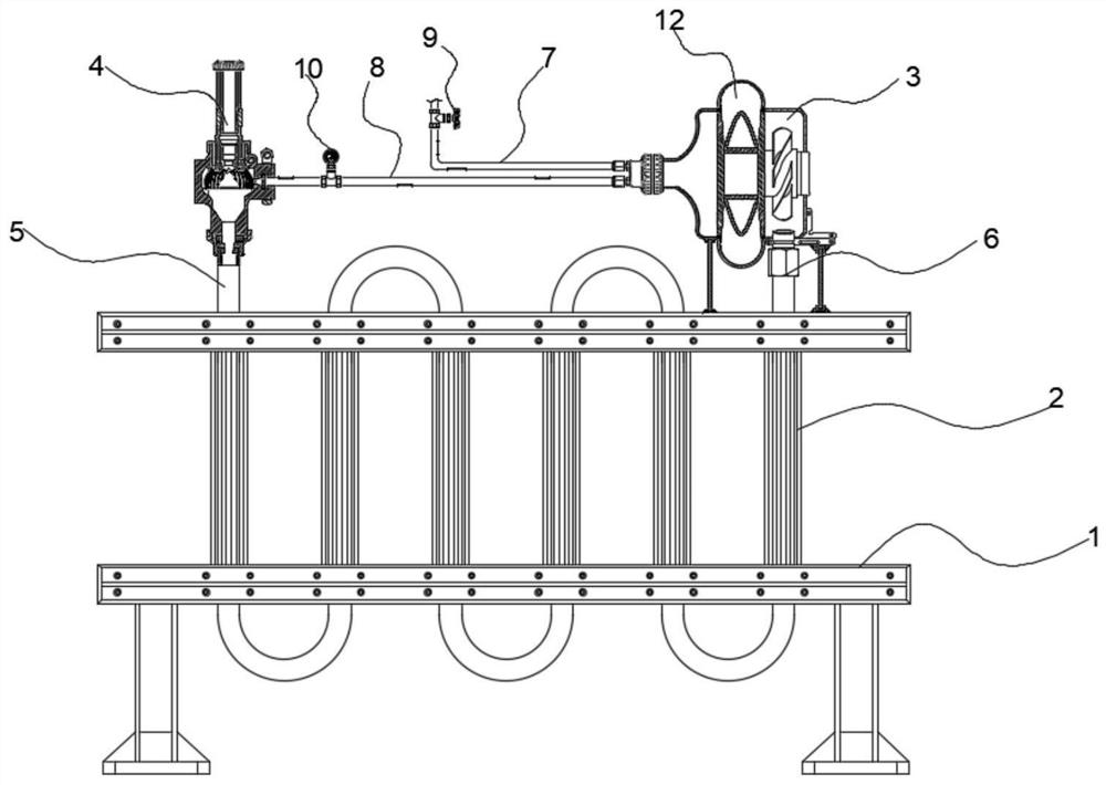
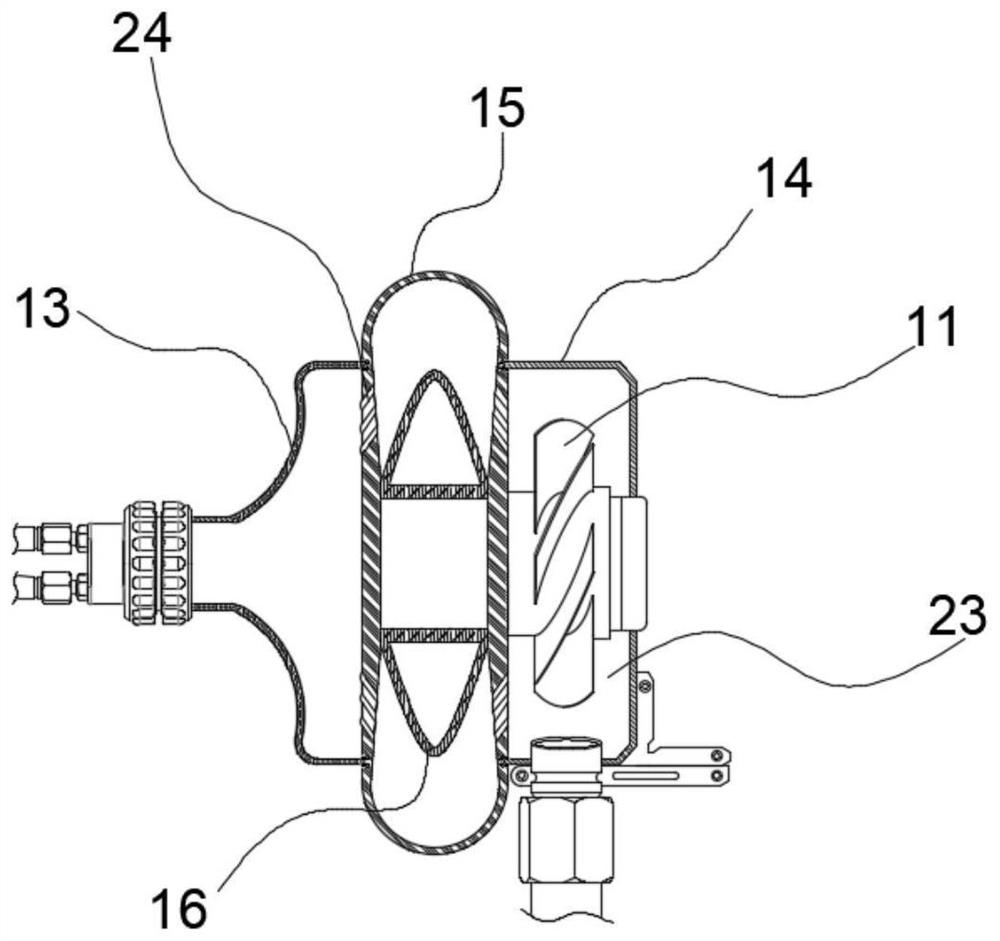
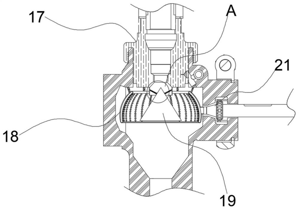
[0037] see figure 1 , in an embodiment of the present invention, an air-temperature evaporator with automatic defrosting, which includes a fixed frame 1, a finned tube set 2, a secondary vaporization pressurization assembly 3, and a liquid inlet defrosting assembly 4, wherein the fixed The frame 1 is used to arrange and fix the finned tube group 2, the left end of the finned tube group 2 is the liquid inlet 5, and the right end is the air outlet 6, and the upper end of the liquid inlet 5 is fixedly installed with a liquid inlet and defrosting assembly 4. In order to initially heat up and vaporize the low-temperature liquid entering the finned tube group 2, wherein the finned tube group 2, the secondary vaporization pressurization component 3 and the liquid inlet defrosting component 4 are all made of aluminum alloy materials, not only High thermal conductivity and light weight make the operation of the whole device more stable;

[0038] The secondary vaporization pressurizati...


PUM


Abstract

The invention discloses an air-temperature carburetor with automatic defrosting, which includes a fixed frame, a finned tube group, a secondary vaporization pressurization assembly, and a liquid-inlet defrosting assembly, wherein the fixed frame is used for arranging and fixing the fins Tube group, the left end of the finned tube group is the liquid inlet, and the right end is the gas outlet, and the upper end of the liquid inlet is fixedly installed with a liquid inlet defrosting assembly, so as to initially heat up the cryogenic liquid entering the finned tube group Vaporization; the secondary vaporization pressurization assembly communicates with the gas outlet, and the bottom of the secondary vaporization pressurization assembly is fixed on the fixed frame through a support frame, and the left end of the secondary vaporization pressurization assembly is respectively passed through a single The valve is connected with a collection pipe and a return pipe. The one-way valve is used to prevent the gas from flowing back into the secondary pressurization assembly. The collection pipe is used to collect part of the dry gas. The left end of the return pipe is connected to the liquid inlet defrosting assembly connected.

Description

technical field [0001] The invention belongs to the technical field of carburetors, in particular to an air-temperature carburetor with automatic defrosting. Background technique [0002] The air-temperature evaporator is a high-efficiency energy-saving heat exchange device that exchanges heat between the ambient temperature and the low-temperature liquid in the heat exchange tube through natural convection of the air, and completely evaporates the low-temperature liquid into a gas. However, according to investigations, it is found that the existing Air temperature evaporators often have the following problems: [0003] 1. There is no defrosting function, resulting in frosting after the air-temperature vaporizer works for a period of time, which not only affects the vaporization efficiency of the subsequent low-temperature liquid, but also easily causes damage to components; [0004] 2. Use the auxiliary heating device to defrost the air-temperature evaporator, which increa...

Claims


Application Information

Patent Timeline
Patent Type & Authority Patents(China)
IPC IPC(8): F17C9/02F17C13/10
CPCF17C9/02F17C13/10F17C2227/03F17C2223/0153F17C2225/0123
Inventor 吴桂兰曾旭高风阳
Owner 苏州杜尔气体化工装备有限公司
Learn More