Light source driver
A driver and light source technology, applied in electrical components and other directions, can solve the problems of not being able to simulate sunlight to present different illuminance, and not being able to provide passengers with an excellent ride experience, so as to optimize the ride experience, improve the ride environment, and improve the lighting quality. Effect
- Summary
- Abstract
- Description
- Claims
- Application Information
AI Technical Summary
Problems solved by technology
Method used
Image
Examples
Embodiment 1
[0029] This embodiment provides a train lamp. The train lamp provided by this embodiment can be used to simulate sunlight in the compartments of high-speed trains, EMU trains, subway trains, light rail trains and other types of trains. The type of train is here Not limited.
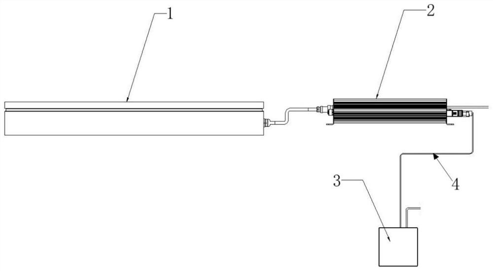
[0030] Such as figure 1 As shown, the train lamp provided by this embodiment includes a control panel 2, a driver 3 and a lighting system 1, the driver 3 includes an input terminal and an output terminal, the input terminal is electrically connected to the control panel 2 through the CAN communication line 4, and the output terminal is connected to the control panel 2. The lighting system 1 is electrically connected, the control panel 2 sets lighting parameters, and the driver 3 adjusts the PWM duty cycle according to the lighting parameters set by the control panel 2 to drive the lighting system 1 to simulate sunlight exposure.
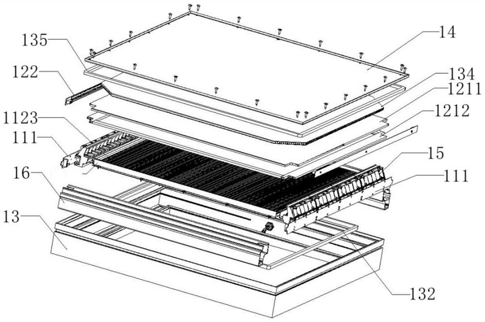
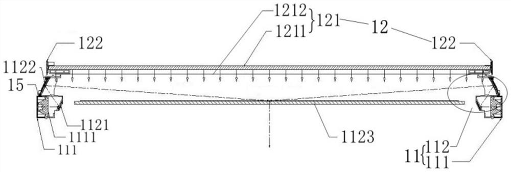
[0031] Such as Figures 2 to 6 As shown, the lighting system 1 includes a...
Embodiment 2
[0043] This embodiment provides a light source driver, which is used to drive the lighting system 1 of the train lamp described in Embodiment 1 to simulate sunlight on the train. The light source driver provided in this embodiment is the driver 3 in Embodiment 1. , this embodiment will further elaborate on the driver 3 .
[0044] The driver 3 includes an input terminal and an output terminal, the input terminal is connected to the external control signal terminal through the CAN communication line, that is, the control panel 2 in the first embodiment, the output terminal is electrically connected to the lighting system 1, and the driver 3 receives the external control signal according to the input terminal. , that is, the control signal of the control panel 2 to adjust the PWM duty cycle to drive the lighting system 1 to simulate sunlight.
[0045] Such as Figure 8 As shown, the driver 3 includes an upper cover 31, an end plate 32, a bottom case 33, a power supply 34 and a s...
PUM
 Abstract
Description
Claims
Application Information
 - R&D
- Intellectual Property
- Life Sciences
- Materials
- Tech Scout
- Unparalleled Data Quality
- Higher Quality Content
- 60% Fewer Hallucinations
Browse by: Latest US Patents, China's latest patents, Technical Efficacy Thesaurus, Application Domain, Technology Topic, Popular Technical Reports.
© 2025 PatSnap. All rights reserved.Legal|Privacy policy|Modern Slavery Act Transparency Statement|Sitemap|About US| Contact US: help@patsnap.com


