
Humidifying device of respiratory support equipment

A technology that supports equipment and humidification, and is applied in the direction of respirators, etc., which can solve the problems of cumbersome pressure balance pipeline structure and achieve the effect of prolonging the water replenishment time

Pending Publication Date: 2021-01-29
HUNAN MICOME ZHONGJIN MEDICAL SCI & TECH DEV CO LTD
View PDF5 Cites 0 Cited by
  • Summary
  • Abstract
  • Description
  • Claims
  • Application Information

AI Technical Summary

Problems solved by technology

[0004] In order to overcome the problems in the prior art, the present invention provides a humidification device for respiratory support equipment, which aims to solve the problem that the existing humidification device can only supply water to the humidification chamber through a single channel of the water supply chamber and the pressure balance pipeline structure cumbersome questions

Method used


Image

  • Humidifying device of respiratory support equipment
  • Humidifying device of respiratory support equipment
  • Humidifying device of respiratory support equipment

Examples


Embodiment 1

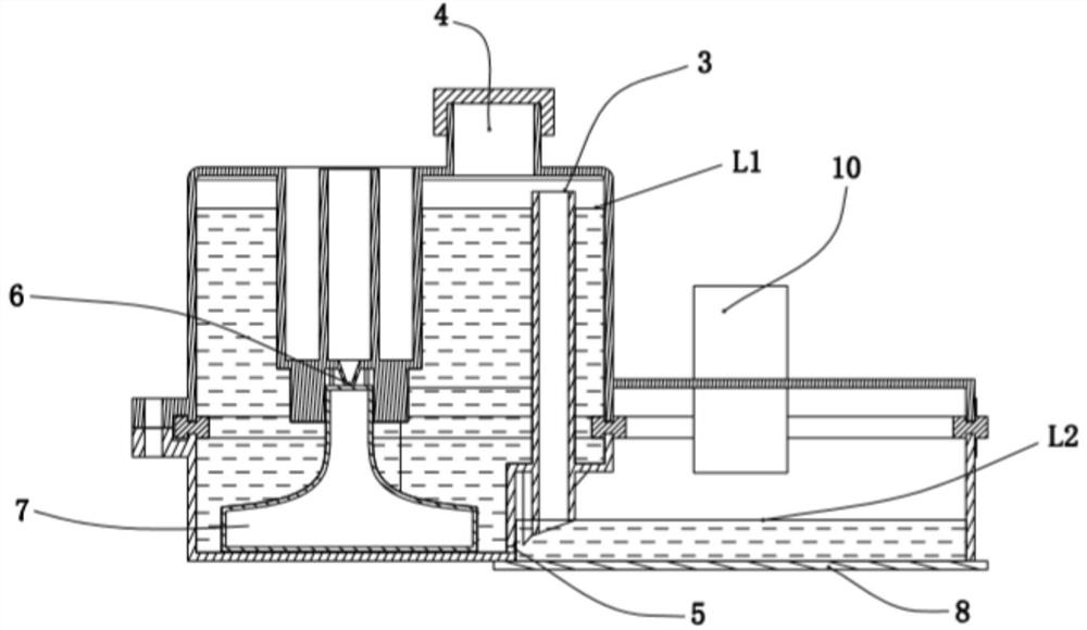
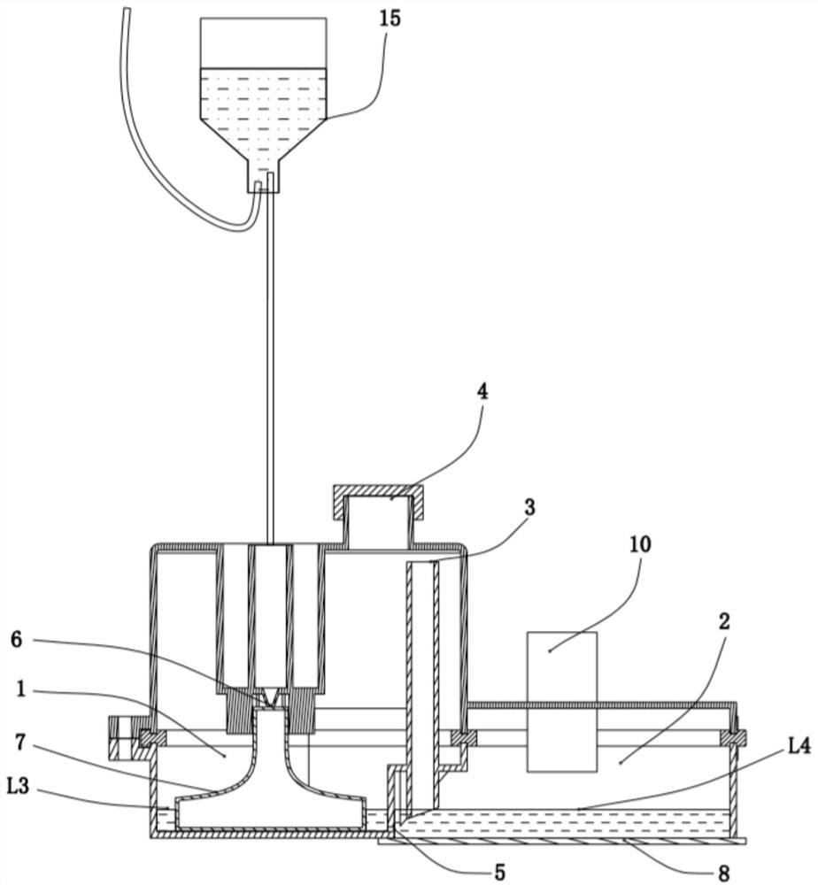
[0052] The water replenishment chamber 1 and the humidification chamber 2 are divided into partitions through the interlayer board, and the interlayer board is provided with installation holes, and the pressure balance pipe 9 is installed on the interlayer board through the installation holes.

[0053] The upper nozzle 91 of the pressure balance pipe 9 extends to the top of the water level of the water supply chamber 1 , and the lower nozzle 92 extends to be equal to the water level of the humidification chamber 2 .

[0054] When the ventilator is working, both the water supply chamber 1 and the humidification chamber 2 are in a closed state to prevent dust from entering the chambers and contaminating the humidification water. The water replenishment chamber 1 replenishes water through the water replenishment port 4 and the intravenous injection port 6 . The upper nozzle 91 of the pressure balance pipe 9 extends to the top of the water level of the water supply chamber 1, and ...

Embodiment 2

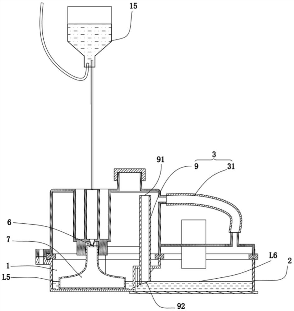
[0057] As a further improvement of the first embodiment, the pressure balance channel 3 further includes a first communication pipe 31 , and the first communication pipe 31 is located outside the humidification chamber 2 . One end of the first communication pipe 31 communicates with the water supply chamber 1 and is located above the water level of the water supply chamber 1; the other end of the first communication pipe 31 communicates with the humidification chamber 2 and is located above the water level of the humidification chamber 2 .

[0058] When the ventilator is working, both the water supply chamber 1 and the humidification chamber 2 are in a closed state. When using intravenous injection to replenish water, the infusion soft bag replenishes water into the water replenishment chamber 1 through the intravenous injection port 6 . The water in the water supply chamber 1 flows to the humidification chamber 2 through the communication hole 5 . If the lower nozzle 92 of ...

Embodiment 3

[0061] refer to Figure 4 , as another specific embodiment of this solution, the pressure balance channel 3 includes a pressure balance tube 9 , the upper nozzle 91 of the pressure balance tube 9 communicates with the water supply chamber 1 , and the lower nozzle 92 extends to the bottom of the humidification chamber 2 . The pressure balance pipe 9 is located on the humidification chamber 2, the pressure balance channel 3 also includes a second communication pipe 32, the upper nozzle 91 communicates with the humidification chamber 2 through the second communication pipe 32, and the lower pipe of the pressure balance pipe 9 The port 92 extends until the water level of the humidification chamber 2 is equal.

[0062] Specifically, an installation hole is provided on the top of the humidification chamber 2, and the pressure balance pipe 9 is installed on the humidification chamber 2 through the installation hole. The lower nozzle 92 extends until the water level of the humidifica...


PUM


Abstract

The invention discloses a humidifying device of respiratory support equipment. The device comprises a box body, a water supplementing chamber and a humidifying chamber are arranged in the box body ina partitioned mode, and the water supplementing chamber is communicated with the humidifying chamber through a pressure balance channel; the water supplementing chamber supplements water into the humidifying chamber in a storage mode or / and an intravenous injection mode, wherein a water supplementing opening is formed in the top end of the water supplementing chamber, and the bottom is communicated with the humidifying chamber through a communicating hole; the water supplementing chamber is further provided with an intravenous injection port and is internally provided with a floating ball, andthe floating ball can be far away from or close to the intravenous injection port; and a heating device is arranged in the humidifying chamber. According to the humidifying device, the water supplementing chamber and the humidifying chamber are arranged in a partitioned mode, water in the humidifying chamber can be heated to a designated humidifying temperature in a short time, and the floating ball can be prevented from being burnt out under the empty burning condition of the humidifying chamber. The water supplementing chamber supplements water to the humidifying chamber, so that the watersupplementing time of the humidifying chamber is prolonged, and application scenes with different requirements are met.

Description

technical field [0001] The invention belongs to the technical field of respiratory equipment, and in particular relates to a humidification device of respiratory support equipment. Background technique [0002] In respiratory support equipment such as non-invasive ventilator or high-flow non-invasive respiratory humidification therapy device, before the air of the ventilator enters the human respiratory system, a humidification device is used to humidify the air of the ventilator. In the humidification device, hot water is heated to generate hot steam, and the air of the ventilator is humidified by hot steam. The existing humidification device generally uses floating balls to replenish water. [0003] Chinese patent application CN111388834A discloses a humidification device for respiratory support equipment, including a box body, a water supply chamber 1 and a humidification chamber 2 are arranged in the box body, and the water supply chamber 1 and the humidification chamber...

Claims


Application Information

Patent Timeline
Patent Type & Authority Applications(China)
IPC IPC(8): A61M16/16
CPCA61M16/165A61M16/162
Inventor 陈文戴征
Owner HUNAN MICOME ZHONGJIN MEDICAL SCI & TECH DEV CO LTD
Learn More