
Fire prevention and control device for V2G direct-current charging pile

A DC charging pile and fire technology, applied in charging stations, electric vehicle charging technology, electric vehicles, etc., can solve problems such as the inability to exchange V2G DC charging pile information, the inability to install V2G DC charging piles, and the inability to eliminate fires, etc.

Pending Publication Date: 2021-01-29
SGCC SMART ENERGY & ELECTRIC TRANSPORTATION TECH INNOVATION CENT (SUZHOU) CO LTD
View PDF0 Cites 1 Cited by
  • Summary
  • Abstract
  • Description
  • Claims
  • Application Information

AI Technical Summary

Problems solved by technology

[0003] However, the existing fire prevention and control devices adopt a modular design, which is too large to be installed in the V2G DC charging pile; and the existing fire prevention and control devices widely use fire smoke alarms. It can only provide early warning but cannot eliminate the fire; and the existing fire prevention and control device has a single fire prevention detection method, and when there is a detection failure, it cannot detect the fire; and the existing fire prevention and control device operates independently and cannot Interact with the V2G DC charging pile for information. When a fire occurs, the V2G DC charging pile cannot disconnect the main circuit, and the fire will cause further damage
Therefore, for a fire prevention and control device for V2G DC charging piles, the problems we have to solve are the large size, the inability to eliminate the fire source, the single fire detection method, and the inability to interact with V2G DC charging piles.

Method used


Image

  • Fire prevention and control device for V2G direct-current charging pile
  • Fire prevention and control device for V2G direct-current charging pile
  • Fire prevention and control device for V2G direct-current charging pile

Examples


Embodiment Construction

[0019] The preferred embodiments of the present invention will be described in detail below in conjunction with the accompanying drawings, so that the advantages and features of the present invention can be more easily understood by those skilled in the art, so as to define the protection scope of the present invention more clearly.

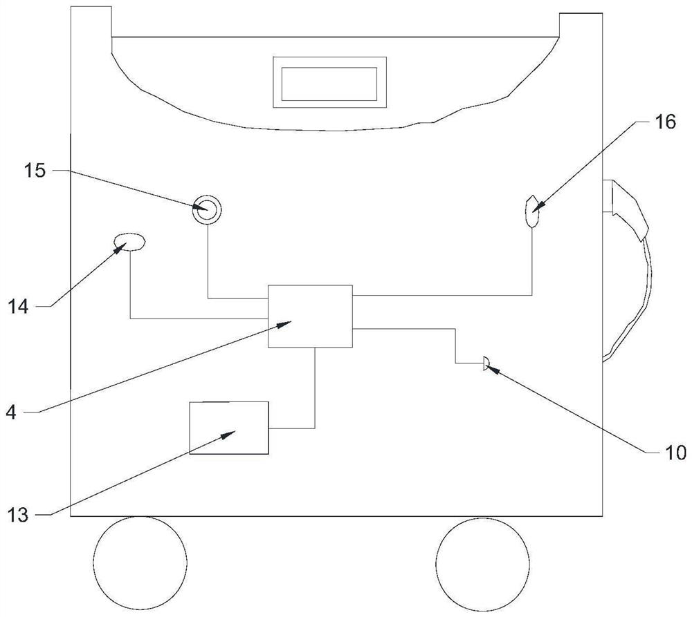
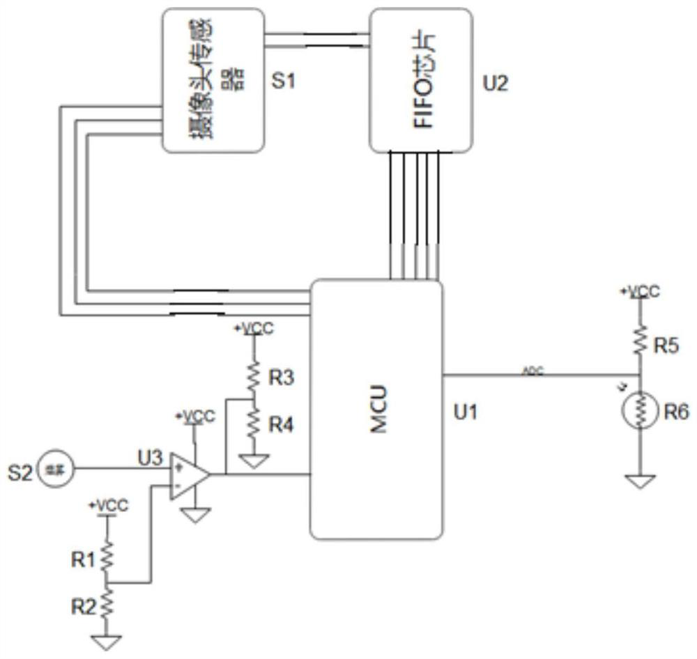
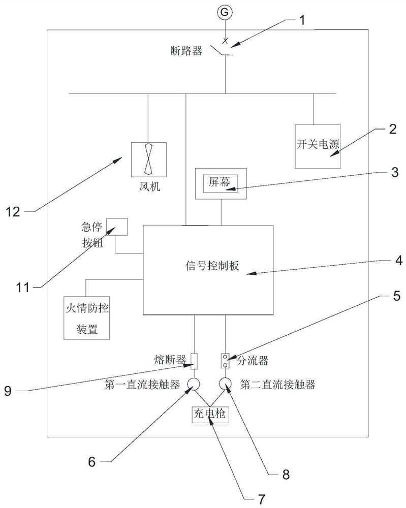
[0020] See attached Figure 1-4 As shown, in this embodiment, a fire prevention and control device for V2G DC charging piles includes a chassis arranged in the body of the V2G DC charging pile, and a temperature sensor 14 for detecting real-time temperature information is provided on the chassis for detecting Smoke sensor unit 16 for real-time smoke concentration information, camera unit 15 for shooting real-time fire information, fire extinguishing unit 10 for releasing fire extinguishing agent and equipped with fire extinguishing agent, and a fire extinguishing agent recovery unit for inhaling fire extinguishing agent is arranged in the cabinet ...


PUM


Abstract

The invention discloses a fire prevention and control device for a V2G direct-current charging pile. The fire prevention and control device for the V2G direct-current charging pile comprises a case arranged in the V2G direct-current charging pile, wherein a temperature sensor used for detecting real-time temperature information, a smoke sensor unit used for detecting real-time smoke concentrationinformation, a camera unit used for shooting real-time fire information, and a fire extinguishing unit used for releasing a fire extinguishing agent and containing the fire extinguishing agent are arranged on the case; a fire extinguishing agent recovery unit used for sucking the fire extinguishing agent is arranged in the case; and the temperature sensor, the smoke sensor unit, the camera unit, the fire extinguishing unit and the fire extinguishing agent recovery unit are all electrically connected with a signal control panel in a pile body of the V2G direct-current charging pile. The invention aims to provide the fire prevention and control device for the V2G direct-current charging pile which can be installed in the V2G direct-current charging pile, three fire prevention detection methods are provided, information interaction with the V2G direct-current charging pile can be carried out, and when a fire occurs, the fire can be eliminated.

Description

technical field [0001] The invention relates to the field of V2G DC charging piles, in particular to a fire prevention and control device for V2G DC charging piles. Background technique [0002] With the development of electric vehicles, more and more families choose electric vehicles for travel. In order to solve the difficult problem of charging and discharging, V2G DC charging piles came into being, because of their excellent performance in charging and discharging technology, which greatly improves the user experience. However, during the use of electric vehicle charging piles, due to factors such as circuit design defects, aging electrical components, and external environment, it is easy to cause fire accidents at the charging piles, and more seriously, it will cause the vehicle to burn. At present, fire prevention and control devices are used to prevent fire accidents in V2G DC charging piles. [0003] However, the existing fire prevention and control devices adopt a...

Claims


Application Information

Patent Timeline
IPC IPC(8): A62C3/16A62C31/00A62C31/28A62C37/00B60L53/31
CPCA62C3/16A62C31/00A62C31/28A62C37/04B60L53/31Y02T10/70Y02T10/7072Y02T90/12
Inventor 贾俊国周凌霄李悦
Owner SGCC SMART ENERGY & ELECTRIC TRANSPORTATION TECH INNOVATION CENT (SUZHOU) CO LTD
Learn More