
Clamping device based on spherical workpiece punching function

A technology for clamping devices and workpieces, applied in positioning devices, driving devices, metal processing machinery parts, etc., can solve problems such as troubles, fixtures that cannot clamp spherical workpieces, and damage to the surface of workpieces

Inactive Publication Date: 2021-01-29
台州市零动机械科技有限公司
View PDF0 Cites 0 Cited by
  • Summary
  • Abstract
  • Description
  • Claims
  • Application Information

AI Technical Summary

Problems solved by technology

[0002] The drilling of spherical workpieces in numerical control machining is relatively special. Common clamps cannot clamp spherical workpieces when drilling, and they are easy to shift during drilling and damage the surface of workpieces when clamping, which is very troublesome. A clamping device based on the function of punching a spherical workpiece can solve the above problems

Method used


Image

  • Clamping device based on spherical workpiece punching function
  • Clamping device based on spherical workpiece punching function
  • Clamping device based on spherical workpiece punching function

Examples


Embodiment Construction

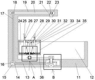
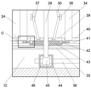
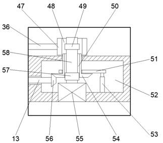
[0014] Combine below Figure 1-4 The present invention is described in detail, wherein, for the convenience of description, the orientations mentioned below are defined as follows: figure 1 The up, down, left, right, front and back directions of the projection relationship itself are the same.

[0015]A clamping device based on the punching function of a spherical workpiece according to the present invention includes a machine tool 11, the machine tool 11 is provided with a moving cavity 12 with an upward opening, and a workpiece seat 35 is provided for lateral movement in the moving cavity 12, The workpiece seat 35 is provided with a driving chamber 24, and the upper wall of the driving chamber 24 is fixed with an auxiliary motor 28, and the lower end of the auxiliary motor 28 is connected with an auxiliary motor shaft 29, and the lower end of the auxiliary motor shaft 29 runs through and Rotationally connected to the lower wall of the workpiece seat 35, the center of the lo...


PUM


Abstract

The invention discloses a clamping device based on a spherical workpiece punching function. The clamping device comprises a machine tool, wherein a moving cavity with an upward opening is arranged inthe machine tool; a workpiece base is transversely and movably arranged in the moving cavity; an actuating chamber is arranged in the workpiece base; an auxiliary motor is fixedly arranged in the upper wall of the driving cavity; the lower end of the auxiliary motor is in power connection with an auxiliary motor shaft; and the lower end of the auxiliary motor shaft penetrates through and is rotationally connected to the lower wall of the workpiece base. According to the clamping device, a left arc-shaped clamping block and a right arc-shaped clamping block are used for clamping a spherical workpiece to conduct drilling work on the spherical workpiece; when the spherical workpiece is placed on the arc-shaped clamping blocks, the angles and the left-right widths of the arc-shaped clamping blocks are adjusted, so that the clamping blocks clamp the spherical workpiece left and right at the firm positions; and after the workpiece is clamped, the spherical workpiece can be driven to move upand down and move back and forth and left and right, so that the drilling position and depth are adjusted.

Description

technical field [0001] The invention relates to the related field of numerical control machining, in particular to a clamping device based on the function of punching a spherical workpiece. Background technique [0002] The drilling of spherical workpieces in numerical control machining is relatively special. Common clamps cannot clamp spherical workpieces when drilling, and they are easy to shift during drilling and damage the surface of workpieces when clamping, which is very troublesome. A clamping device based on the punching function of a spherical workpiece can solve the above problems. Contents of the invention [0003] In order to solve the above problems, a clamping device based on the function of punching a spherical workpiece is designed in this example. A clamping device based on the function of punching a spherical workpiece in this example includes a machine tool. A moving chamber, a workpiece seat is provided for lateral movement in the moving chamber, a dr...

Claims


Application Information

Patent Timeline
Patent Type & Authority Applications(China)
IPC IPC(8): B23B41/00B23B47/06B23Q3/00B23Q1/25
CPCB23B41/00B23Q1/25B23Q3/00B23Q5/10
Inventor 史立号
Owner 台州市零动机械科技有限公司
Learn More