Drilling device capable of preventing scraps from splashing

A drilling device and anti-chip technology, which is applied in the direction of boring/drilling, drilling/drilling equipment, boring machine/drilling machine parts, etc., can solve the problem of drilling position deviation, etc., to prevent debris from splashing, prevent splatter effect

Inactive Publication Date: 2021-06-18
胡广荣
View PDF0 Cites 0 Cited by
  • Summary
  • Abstract
  • Description
  • Claims
  • Application Information

AI Technical Summary

Problems solved by technology

[0002] During the drilling process of the pipe, debris will be generated. Part of the debris will be carried out with the drill bit or splashed, and the other part of the debris will enter the pipe. The splashed debris needs to be cleaned later, while The debris that enters the pipe needs to be poured out manually. It is more convenient for drilling straight pipes, but for the drilling of curved pipes, the position of the pipe needs to be fixed. Generally, it is hand-held, which is easy to cause deviation of the drilling position.

Method used


Image

  • Drilling device capable of preventing scraps from splashing
  • Drilling device capable of preventing scraps from splashing
  • Drilling device capable of preventing scraps from splashing

Examples


specific Embodiment approach 1

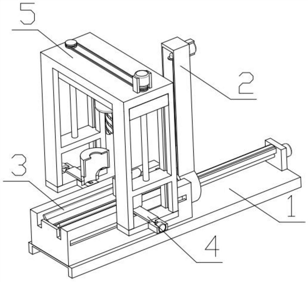
[0034] Combine below Figure 1-14 Description of this embodiment, a drilling device that prevents chips from flying around, including a distance-adjustable base 1, an adjustment blowpipe mechanism 2, a pipe diameter placement mechanism 3, an anti-splash mechanism 4, and a drilling mechanism 5. The adjustment blowpipe Mechanism 2 is threadedly connected to the distance-adjustable base 1, the pipe diameter placement mechanism 3 is fixedly installed on the distance-adjustable base 1, the splash-proof mechanism 4 is slidably installed on the distance-adjustable base 1, and the drilling mechanism 5 is fixedly installed on the splash-proof Institution 4 on.

specific Embodiment approach 2

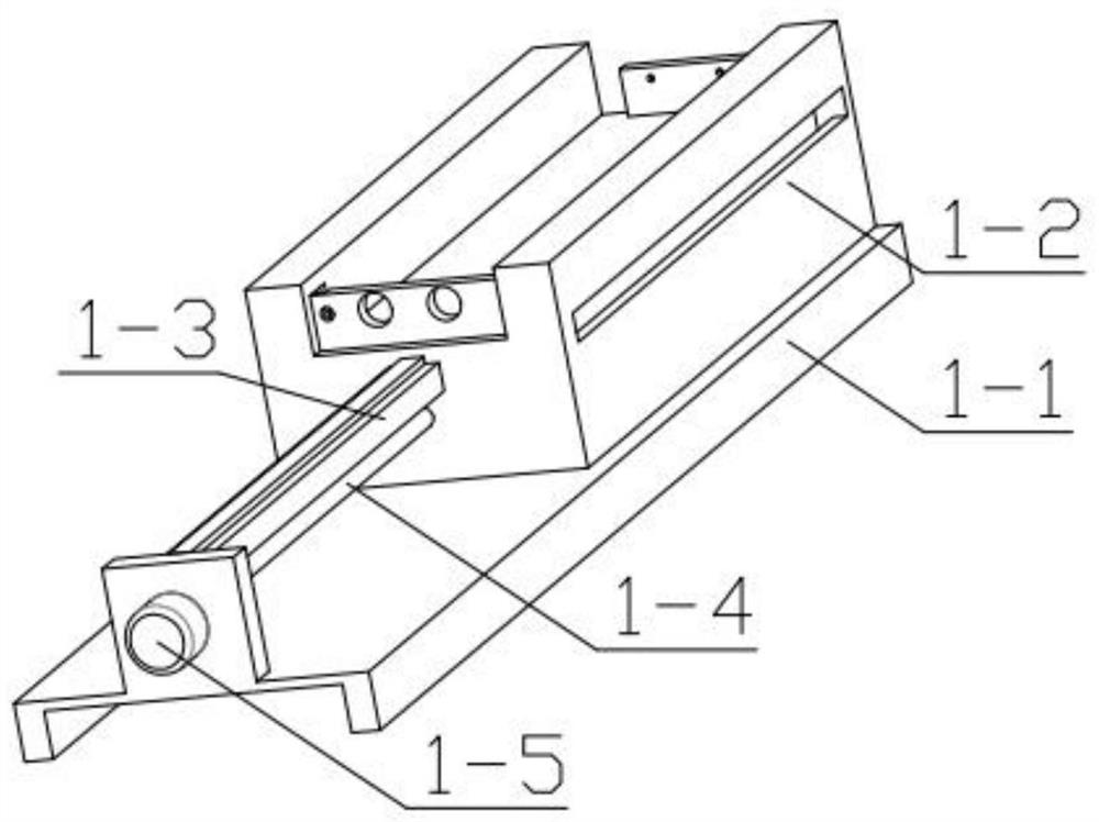
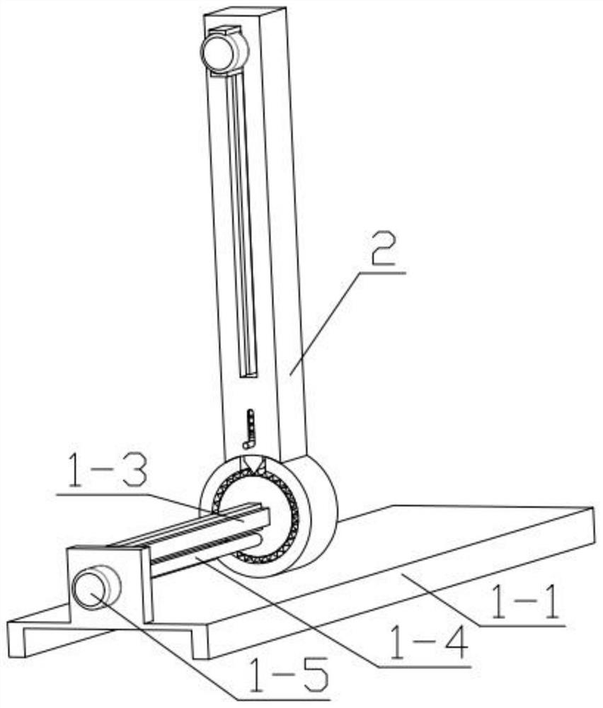
[0036] Combine below Figure 1-14Describe this embodiment, this embodiment will further explain Embodiment 1, the distance adjustable base 1 includes a base plate 1-1, a mounting seat 1-2, a track plate 1-3, an adjustment threaded rod 1-4, an adjustment The motor 1-5 and the adjusting motor 1-5 are fixedly installed on the base plate 1-1, the base plate 1-1 is fixedly installed with a mounting base 1-2, and the mounting base 1-2 is fixedly equipped with a track plate 1- 3. The other end of the track plate 1-3 is fixedly installed on the base plate 1-1, the output end of the adjusting motor 1-5 is fixedly installed with an adjusting threaded rod 1-4, and the other end of the adjusting threaded rod 1-4 is rotated and installed In the groove provided on the mounting base 1-2.

specific Embodiment approach 3

[0038] Combine below Figure 1-14 Describe this embodiment, this embodiment will further explain the second embodiment, the adjustment blow pipe mechanism 2 includes a grooved plate 2-1, a rotating ring 2-2, a positioning gear 2-3, and a triangular positioning member 2-4 , internal spring 2-5, fan 2-6, fan seat 2-7, sliding part 2-8, exhaust hose 2-9, positioning gear part 2-3 is slidably installed on track plate 1-3, positioning gear The part 2-3 is threadedly connected with the adjusting threaded rod 1-4, the positioning gear part 2-3 is rotatably installed with a rotating ring 2-2, and the rotating ring 2-2 is fixedly installed with a grooved plate 2-1 and a grooved plate 2 The triangular positioning part 2-4 is slidably installed in the groove of -1, the internal spring 2-5 is fixedly installed on the triangular positioning part 2-4, and the other end of the internal spring 2-5 is fixedly mounted on the groove plate 2-1 In the groove, a fan 2-6 is fixedly installed on the...


PUM


Abstract

The invention relates to the related field of pipe processing machinery, in particular to a drilling device capable of preventing scraps from splashing. The drilling device comprises a distance-adjustable base, an adjusting and pipe blowing mechanism, a pipe caliber placing mechanism, a splashing preventing mechanism and a drilling mechanism, the adjusting and pipe blowing mechanism is in threaded connection with the distance-adjustable base, the pipe caliber placing mechanism is fixedly installed on the distance-adjustable base, the splashing preventing mechanism is installed on the distance-adjustable base in a sliding manner, and the drilling mechanism is fixedly installed on the splashing preventing mechanism. According to the device, the scraps can be prevented from splashing, the residual scraps in a pipe can be discharged, the scraps are prevented from being left in the pipe, meanwhile, later cleaning is facilitated, the bent pipe can be conveniently drilled at any angle through the device, and the device is convenient and fast to use.

Description

technical field [0001] The invention relates to the related field of pipe processing machinery, in particular to a drilling device capable of preventing chip splashing. Background technique [0002] During the drilling process of the pipe, debris will be generated. Part of the debris will be carried out with the drill bit or splashed, and the other part of the debris will enter the pipe. The splashed debris needs to be cleaned later, while The debris entering the pipe needs to be manually poured out. It is more convenient for drilling straight pipes, but for the drilling of curved pipes, the position of the pipe needs to be fixed. Generally, hand-holding is used, which may easily cause deviations in the drilling position. Contents of the invention [0003] The main technical problem to be solved by the present invention is to provide a drilling device that prevents debris from flying around. This device can avoid debris from flying around, discharge debris remaining in the...

Claims


Application Information

Patent Timeline
Patent Type & Authority Applications(China)
IPC IPC(8): B23B41/00B23B47/00B23Q11/08B23Q11/00
CPCB23B41/00B23B47/00B23Q11/00B23Q11/0042B23Q11/005B23Q11/08
Inventor 胡广荣
Owner 胡广荣
Why Eureka
Try Eureka