Supercharge Your Innovation With Domain-Expert AI Agents!

Automatic polishing device for cold-rolled steel in high-end equipment manufacturing

A polishing device and cold-rolled steel technology, which is applied to grinding drive devices, manufacturing tools, grinding/polishing equipment, etc., can solve problems such as inability to polish cold-rolled steel

Active Publication Date: 2021-01-29
DONGYANG ZHONGZHOU STRIP
View PDF5 Cites 2 Cited by
  • Summary
  • Abstract
  • Description
  • Claims
  • Application Information

AI Technical Summary

Problems solved by technology

[0005] In order to overcome the current disadvantage of being unable to continuously polish both sides of the cold-rolled steel when polishing the surface of the cold-rolled steel, the technical problem to be solved is to provide a method that can continuously polish both sides of the cold-rolled steel Automatic polishing device for cold-rolled steel in the manufacture of high-end equipment

Method used


Image

  • Automatic polishing device for cold-rolled steel in high-end equipment manufacturing
  • Automatic polishing device for cold-rolled steel in high-end equipment manufacturing
  • Automatic polishing device for cold-rolled steel in high-end equipment manufacturing

Examples


Embodiment 1

[0029] An automatic polishing device for cold-rolled steel in high-end equipment manufacturing, such as Figure 1-4 As shown, it includes a frame 1, a placement assembly 2, a grinding assembly 3 and a pushing assembly 4. The left side of the frame 1 is provided with the placement assembly 2, the right side of the frame 1 is provided with the grinding assembly 3, and the upper middle of the frame 1 is provided with There is push component 4.

[0030] When it is necessary to polish the cold-rolled steel, first place the cold-rolled steel on the placing component 2, and adjust the height of the cold-rolled steel by placing the component 2, and then control the grinding component 3 to start working, and then the worker can manually pass through The pushing component 4 pushes the cold-rolled steel to the right, so that the grinding component 3 grinds the cold-rolled steel. When one side of the cold-rolled steel is polished, the cold-rolled steel can be turned over, and then the pus...

Embodiment 2

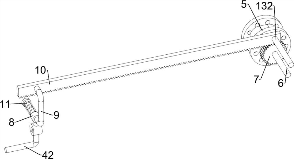
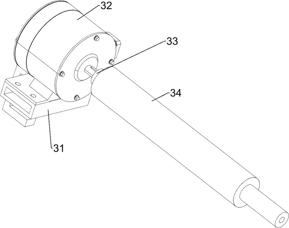
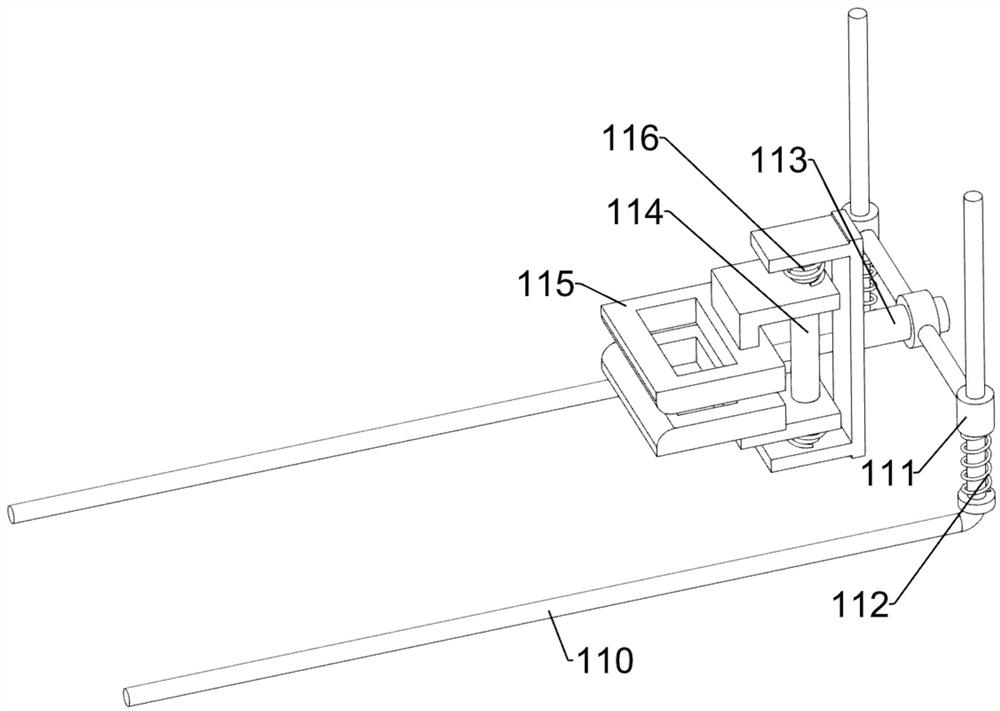
[0038] On the basis of Example 1, such as Figure 4-9 As shown, it also includes a planetary reducer 5, a second rotating shaft 6, a first gear 7, a sliding sleeve 8, a second connecting frame 9, a first rack 10, a second spring 11, a first special-shaped frame 101, a second Fixed frame 12, hollow block 13, first wedge block 14 and the 3rd spring 15, first rotating shaft 33 front sides are provided with planetary reducer 5, planetary reducer 5 front sides are provided with second rotating shaft 6, on the second rotating shaft 6 The key is connected with the first gear 7, the first connecting frame 42 top is connected with the sliding sleeve 8, the sliding type is provided with the second connecting frame 9 on the sliding sleeve 8, the second connecting frame 9 top is connected with the first rack 10, the first The rack 10 meshes with the first gear 7, the second spring 11 is connected between the second connecting frame 9 and the sliding sleeve 8, the front side of the left pa...


PUM


Abstract

The invention relates to a polishing device, in particular to an automatic polishing device for cold-rolled steel in high-end equipment manufacturing. The technical problem to be solved by the invention is to provide an automatic polishing device for cold rolled steel in high-end equipment manufacturing, which can continuously polish two sides of a cold rolled steel plate. The automatic polishingdevice for the cold rolled steel in high-end equipment manufacturing comprises a frame, a placement assembly mounted on the frame, a polishing assembly mounted on the frame, and a pushing assembly mounted on the frame. The pushing assembly drives the cold-rolled steel to move; after the cold-rolled steel moves to make contact with the polishing assembly, the polishing assembly polishes the cold-rolled steel; and after one side of the cold-rolled steel is polished by the polishing assembly, a rotating frame rotates to drive the cold-rolled steel to turn over, and then the pushing assembly drives the cold-rolled steel to reset, so that the other side of the cold-rolled steel is polished.

Description

technical field [0001] The invention relates to a polishing device, in particular to an automatic polishing device for cold-rolled steel in high-end equipment manufacturing. Background technique [0002] Cold-rolled steel refers to steel produced by cold rolling. In high-end equipment manufacturing, cold-rolled steel is widely used. [0003] In some high-end equipment manufacturing, it is necessary to polish the cold-rolled steel first. The worker first places the cold-rolled steel on the polishing device, and the polishing device polishes one side of the cold-rolled steel. When one side of the cold-rolled steel After the polishing is completed, the cold-rolled steel can be removed and turned over, and placed on the polishing device again to polish the other side of the cold-rolled steel, which is time-consuming and laborious for polishing. [0004] Therefore, it is necessary to design an automatic polishing device for cold-rolled steel in high-end equipment manufacturing t...

Claims


Application Information

Patent Timeline
Patent Type & Authority Applications(China)
IPC IPC(8): B24B29/02B24B41/02B24B41/00B24B41/04B24B41/06B24B47/22B24B47/12B08B1/02B08B1/20
CPCB24B29/02B24B41/02B24B41/005B24B41/04B24B41/06B24B47/22B24B47/12B08B1/143B08B1/20
Inventor 曾少燕
Owner DONGYANG ZHONGZHOU STRIP
Features
  • R&D
  • Intellectual Property
  • Life Sciences
  • Materials
  • Tech Scout
  • Unparalleled Data Quality
  • Higher Quality Content
  • 60% Fewer Hallucinations
Learn More