Unmanned aerial vehicle with telescopic vehicle arms

A technology of unmanned aerial vehicle and telescopic machine, applied in the field of unmanned aerial vehicles, can solve the problems of large space occupied, inconvenient transportation of unmanned aerial vehicles, inability to extend and retract the arms, etc., and achieves a convenient adjustment process, avoids shaking, and is not easily deformed and damaged. Effect

Inactive Publication Date: 2021-01-29
江西玉祥智能装备制造有限公司
View PDF6 Cites 8 Cited by
  • Summary
  • Abstract
  • Description
  • Claims
  • Application Information

AI Technical Summary

Problems solved by technology

The collective distance of the rotor is fixed, not as variable as that of general helicopters. By changing the relative speed between different rotors, the magnitude of the single-axis propulsion can be changed, thereby controlling the trajectory of the aircraft. The multi-rotor UAV can take off and land vertically. And hovering, mainly suitable for low-altitude, low-speed, vertical take-off and landing and hovering mission types. Some existing multi-purpose multi-rotor drones cannot be transported and placed because the arms cannot be retracted. Lots of room, room for improvement

Method used


Image

  • Unmanned aerial vehicle with telescopic vehicle arms
  • Unmanned aerial vehicle with telescopic vehicle arms
  • Unmanned aerial vehicle with telescopic vehicle arms

Examples


Embodiment 1

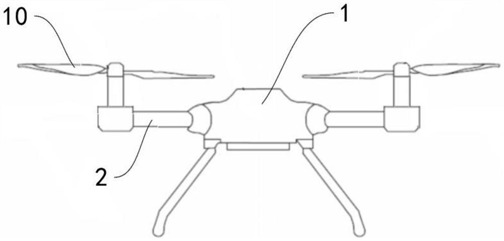
[0033] Refer to the accompanying drawings below Figure 1-Figure 5 Describe the UAV with telescopic arm 2 according to Embodiment 1 of the present invention, the device includes a fuselage 1, an arm 2 and a rotor assembly 10, wherein the arm 2 includes a first arm 3 and a second arm 4 .

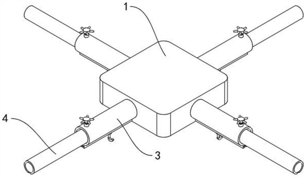
[0034] The first arm 3 is a hollow pipe with both ends open. One end of the first arm 3 is connected to the fuselage 1. The first arm 3 is provided with a fastening shaft that can move back and forth along the radial direction of the first arm 3. 5, and the end of the fastening shaft 5 close to the central axis of the first arm 3 is provided with a flexible pad 6, and the inner peripheral wall of the first arm 3 is provided with a limiting protrusion 7.

[0035] Specifically, refer to figure 2 , image 3 and Figure 4 , taking one of the machine arms 2 as an example, the first arm 3 is a long tube extending in the left and right direction, the first arm 3 is hollow and open at both ends,...

Embodiment 2

[0046] The following describes an unmanned aerial vehicle with a telescopic arm 2 according to Embodiment 2 of the present invention with reference to the accompanying drawings. Embodiment 2 is a further improvement on Embodiment 1.

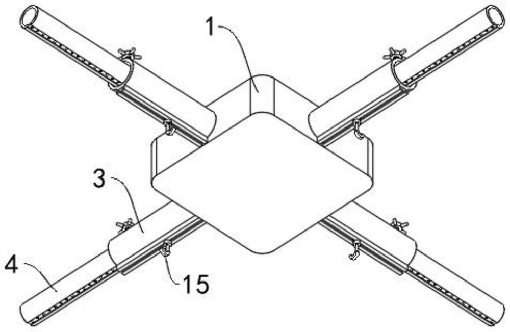
[0047] like image 3 and Figure 5 As shown, the outer peripheral wall of the first arm 3 is provided with a hook 15 that can slide along the axial direction of the first arm 3, and the hook 15 is provided with a fixing part 16, and the fixing part 16 is used to fix the hook 15. On the first boom 3, the hook 15 provided can be used to hang some lighter items, thereby improving the carrying capacity of the drone, and the hook 15 can be moved so that its position can be flexibly adjusted.

[0048] like Figure 7 and Figure 8 As shown, the bottom of the outer peripheral wall of the first arm 3 is fixedly connected to the limit bar 14, and the limit bar 14 is provided with a slideway extending along the axial direction of the first arm 3. The hoo...


PUM


Abstract

The invention discloses an unmanned aerial vehicle with telescopic vehicle arms. The unmanned aerial vehicle comprises a vehicle body, a vehicle arm, a guide groove and a rotor wing assembly, whereinthe vehicle arm comprises a first arm rod and a second arm rod, one end of the first arm rod is connected with the vehicle body, a movable fastening shaft is arranged on the first arm rod, a flexiblepad is arranged at one end of the fastening shaft, and a limiting protrusion is arranged on the inner circumferential wall of the first arm rod; the guide groove extending in the axial direction of the second arm rod and is formed in the peripheral wall of the second arm rod, a plurality of limiting grooves are formed in the groove bottom wall of the guide groove and distributed in the length direction of the guide groove at intervals, the second arm rod slidably extends into the first arm rod, and the limiting protrusions are located in the guide groove; the second arm rod slides to enable the limiting protrusion to be matched with one limiting groove, and the fastening shaft moves to enable the flexible pad to abut against the second arm rod to fix the second arm rod. and the rotor wingassembly is arranged at the end, away from the first arm rod, of the second arm rod, and the device can achieve extension and retraction of the vehicle arm.

Description

technical field [0001] The invention relates to the field of unmanned aerial vehicles, in particular to an unmanned aerial vehicle with telescopic arms. Background technique [0002] A multi-rotor UAV is a UAV with three or more arms. The outer end of each arm is equipped with a lifting thrust mechanism with a motor or an engine as a power source. The motor or generator rotates to drive the rotor, thereby generating thrust. The collective distance of the rotor is fixed, not as variable as that of general helicopters. By changing the relative speed between different rotors, the magnitude of the single-axis propulsion can be changed, thereby controlling the trajectory of the aircraft. The multi-rotor UAV can take off and land vertically. And hovering, mainly suitable for low-altitude, low-speed, vertical take-off and landing and hovering mission types. Some existing multi-purpose multi-rotor drones cannot be transported and placed because the arms cannot be retracted. Lots o...

Claims


Application Information

Patent Timeline
Patent Type & Authority Applications(China)
IPC IPC(8): B64C27/08B64C1/30
CPCB64C27/08B64C1/30B64U10/10
Inventor 邓斌
Owner 江西玉祥智能装备制造有限公司
Why Eureka
Try Eureka