
Micro-nano manufacturing device

A technology of micro-nano manufacturing and conductive nano, which is applied in the field of nano

Pending Publication Date: 2021-01-29
NANJING UNIV
View PDF0 Cites 1 Cited by
  • Summary
  • Abstract
  • Description
  • Claims
  • Application Information

AI Technical Summary

Problems solved by technology

[0003] Based on this, it is necessary to provide a micro-nano manufacturing device for how to improve the processing range of the scanning probe direct writing technology and use the scanning probe to process graphics or devices of various scales

Method used


Image

  • Micro-nano manufacturing device
  • Micro-nano manufacturing device
  • Micro-nano manufacturing device

Examples


Embodiment Construction

[0022] In order to facilitate the understanding of the present invention, the present invention will be described more fully below with reference to the associated drawings. Preferred embodiments of the invention are shown in the drawings. However, the present invention can be embodied in many different forms and is not limited to the embodiments described herein. On the contrary, the purpose of providing these embodiments is to make the disclosure of the present invention more thorough and comprehensive.

[0023] It should be noted that when an element is referred to as being “fixed” to another element, it can be directly on the other element or there can also be an intervening element. When an element is referred to as being "connected to" another element, it can be directly connected to the other element or intervening elements may also be present. As used herein, the terms "vertical", "horizontal", "left", "right", "upper", "lower", "front", "rear", "circumferential" and...


PUM


Abstract

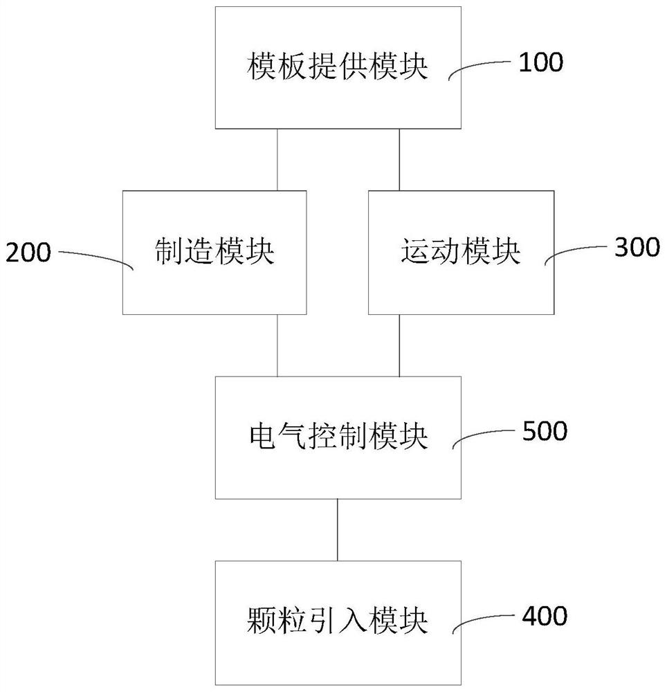
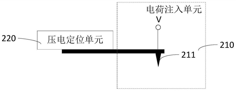
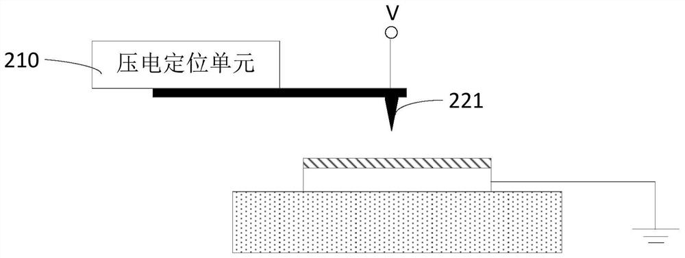
The invention relates to the technical field of nanometer, and discloses a micro-nano manufacturing device. The method comprises the following steps of providing pattern information of a to-be-formedpattern by using a template providing module; fixing a substrate on a motion table unit of a motion module, and driving the substrate to move according to the pattern information through the motion module; positioning the manufacturing module on the substrate to a position where the to-be-formed pattern needs to be formed, and charges are written in to form the to-be-formed pattern. The particle introduction module introduces nanoparticles into the area where the to-be-formed pattern is located to form a to-be-formed structure. The micro-nano manufacturing device provided by the invention cancomplete electrostatic nano-printing manufacturing of micro-nano structures from nanoscale to centimeter level and above, solves the problem that large-scale and cross-scale structures cannot be manufactured by a scanning probe technology, and can realize structure writing in a centimeter or larger range. Precision of local details is ensured to be in a nanoscale.

Description

technical field [0001] The invention relates to the field of nanotechnology, in particular to a micro-nano manufacturing device. Background technique [0002] Among the existing micro-nano manufacturing technologies, direct writing technology has attracted widespread attention due to its advantages of simple manufacturing process, ability to change patterns at any time, and high flexibility. The principle of scanning probe technology in direct writing technology is to use a sharp scanning probe to modify the surface of the sample. Since the scanning probe microscope itself has nanometer-level control accuracy, it can be easily obtained by applying heat and force to the probe. , electricity and other methods to produce nanostructures. The operating techniques of most scanning probes are simple and can be carried out in an atmospheric environment, and micro-nano manufacturing can be carried out by slightly modifying the existing scanning probe microscope. However, since scan...

Claims


Application Information

Patent Timeline
Patent Type & Authority Applications(China)
IPC IPC(8): B81C1/00B82B3/00B82Y40/00
CPCB81C1/00031B81C1/00444B82B3/0004B82B3/0014B82B3/0019B82Y40/00
Inventor 张伟华廖佳梁
Owner NANJING UNIV
Learn More