Eureka AIR delivers breakthrough ideas for toughest innovation challenges, trusted by R&D personnel around the world.

Sewage treatment device capable of reducing sludge discharge

A sewage treatment device and sludge technology, applied in the direction of water/sludge/sewage treatment, sludge treatment, water/sewage treatment, etc., can solve the problems of full settlement of unfavorable sludge, reduced volume of settling tank, excessive sludge content, etc. problems, to achieve the effect of avoiding the reduction of sedimentation effect, reducing sludge discharge, and accelerating sludge drying

Pending Publication Date: 2021-01-29
NANJING GONGCHENG RES INST OF ENERGY CONSERVATION & NEW MATERIALS TECH CO LTD
View PDF6 Cites 2 Cited by
  • Summary
  • Abstract
  • Description
  • Claims
  • Application Information

AI Technical Summary

Problems solved by technology

[0002] Sewage treatment often needs to settle the sludge. After the sludge settles, it will accumulate at the bottom of the settling tank. After a long time, the volume of the settling tank will decrease, which is not conducive to the subsequent full settlement of the sludge, resulting in excessive sludge content when the sewage is discharged. , and the current sewage treatment devices are unable to treat the sludge during use, resulting in a large amount of sludge in the wastewater during use. Therefore, we propose a sewage treatment device that can reduce sludge discharge to solve the above problems

Method used


Image

  • Sewage treatment device capable of reducing sludge discharge
  • Sewage treatment device capable of reducing sludge discharge
  • Sewage treatment device capable of reducing sludge discharge

Examples


Embodiment Construction

[0021] The following will clearly and completely describe the technical solutions in the embodiments of the present invention with reference to the accompanying drawings in the embodiments of the present invention. Obviously, the described embodiments are only some, not all, embodiments of the present invention. Based on the embodiments of the present invention, all other embodiments obtained by persons of ordinary skill in the art without making creative efforts belong to the protection scope of the present invention.

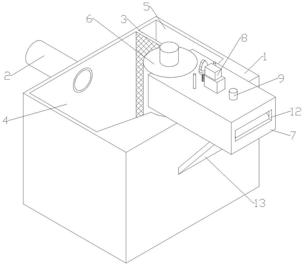
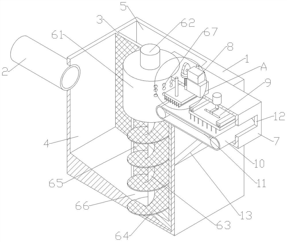
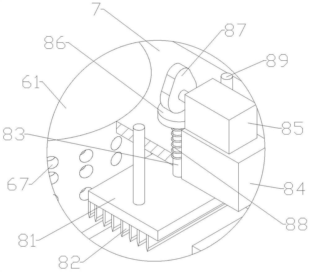
[0022] see Figure 1-4 , the present invention provides a technical solution: a sewage treatment device capable of reducing sludge discharge, comprising a treatment box 1, a filter screen partition 3 is fixedly installed on one side of the inner cavity of the treatment box 1, and two sides of the filter screen partition 3 are formed The settling chamber 4 and the water outlet chamber 5, the sewage pipe 2 is fixedly socketed on the treatment box 1 on one side o...


PUM


Abstract

The invention discloses a sewage treatment device capable of reducing sludge discharge, which comprises a treatment box, the treatment box is divided into a settling cavity and a water outlet cavity by a filter screen partition plate, a sewage pipe sleeves the treatment box on the side of the settling cavity, a sewage discharge mechanism is mounted on the other side of the settling cavity, a fixedbox is mounted at the top of the treatment box, and one end of the fixed box is connected with the sewage discharge mechanism; an outlet is formed in the other end of the fixed box; a conveying beltis installed at the bottom of an inner cavity of the fixed box, a heating plate is installed on the inner wall of the fixed box in the inner cavity of the conveying belt, a chopping mechanism is installed at one end of a fixed box top plate, and a rake rod mechanism is installed at the other end of the fixed box top plate. Sewage enters the settling cavity to be settled, sludge is gathered and increased and then is conveyed into the fixed box through the sewage discharging mechanism in a filter pressing mode, the sludge is extruded into strips through filter pressing and falls on the conveyingbelt, the sludge strips are cut up through the chopping mechanism, the sludge is flatly laid on the conveying belt through the rake rod mechanism, a heating plate can heat the sludge conveniently todry the sludge, and finally the sludge is discharged from the outlet. The purpose of synchronously discharging sludge in sewage treatment is achieved, and sludge discharge is reduced.

Description

technical field [0001] The invention relates to the technical field of sewage treatment, in particular to a sewage treatment device capable of reducing sludge discharge. Background technique [0002] Sewage treatment often needs to settle the sludge. After the sludge settles, it will accumulate at the bottom of the settling tank. After a long time, the volume of the settling tank will decrease, which is not conducive to the subsequent full settlement of the sludge, resulting in excessive sludge content when the sewage is discharged. , and the current sewage treatment devices are unable to treat the sludge during use, resulting in a large amount of sludge in the wastewater during use. Therefore, we propose a sewage treatment device that can reduce sludge discharge to solve the above problems. Contents of the invention [0003] The purpose of the present invention is to provide a sewage treatment device capable of reducing sludge discharge, so as to solve the problems raised...

Claims


Application Information

Patent Timeline
Patent Type & Authority Applications(China)
IPC IPC(8): C02F9/02C02F11/121C02F11/13
CPCC02F1/52C02F1/001C02F11/121C02F11/13C02F2201/002C02F2303/14C02F2303/06
Inventor 孙俊杰
Owner NANJING GONGCHENG RES INST OF ENERGY CONSERVATION & NEW MATERIALS TECH CO LTD
Why Eureka
Eureka Blog
Learn More