
Width limiting device for roads

A technology for limiting width and roads, applied in the field of width limiting devices for roads, can solve the problems of difficult to adjust the width limiting distance, heavy workload, poor safety performance, etc. Effect

Inactive Publication Date: 2021-01-29
李好宣
View PDF0 Cites 2 Cited by
  • Summary
  • Abstract
  • Description
  • Claims
  • Application Information

AI Technical Summary

Problems solved by technology

[0003] At many newly constructed road intersections, width-limiting piers will be installed to restrict the entry of large vehicles. At present, most of the width-limiting piers are directly poured with cement, which is a one-time concrete pouring. The width-limiting piers are mainly used to restrict large vehicles. Drive into the crushed road, but it is not easy to adjust the distance of the width limit after placing it, and use a forklift or crane to dismantle it after use, the workload is heavy, and the safety performance is poor during use, and the vehicle hits the width limit at night Shidun reports happen from time to time

Method used


Image

  • Width limiting device for roads
  • Width limiting device for roads
  • Width limiting device for roads

Examples


Embodiment 1

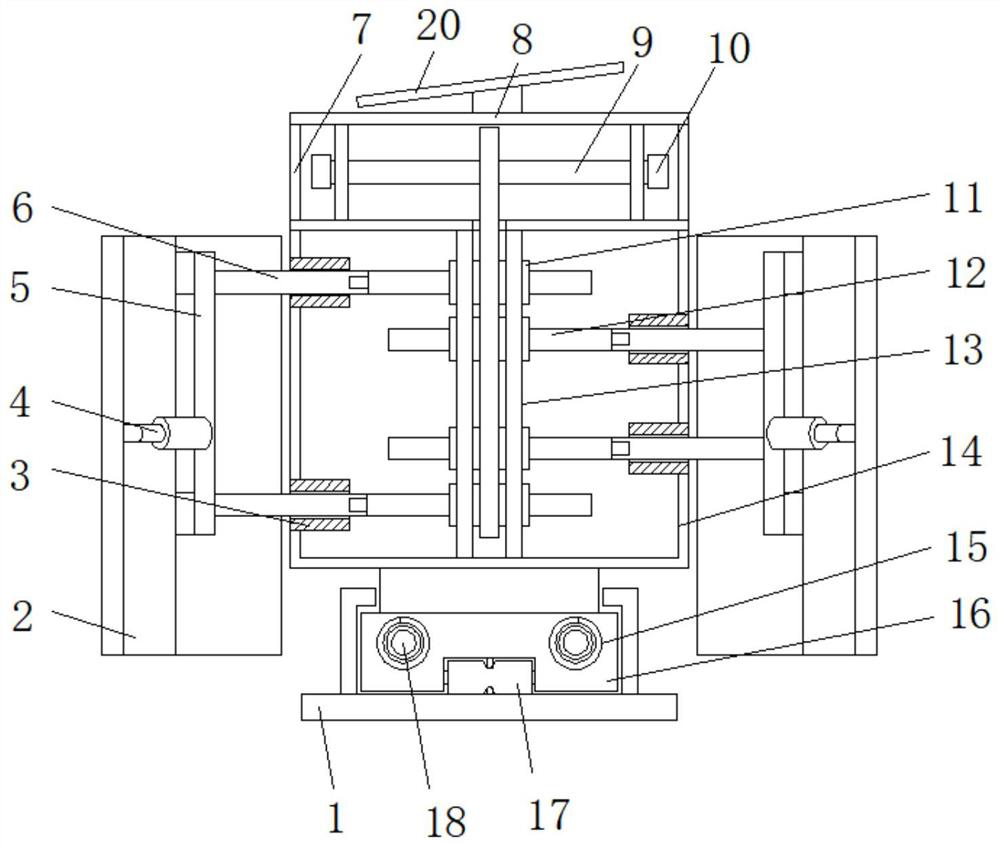
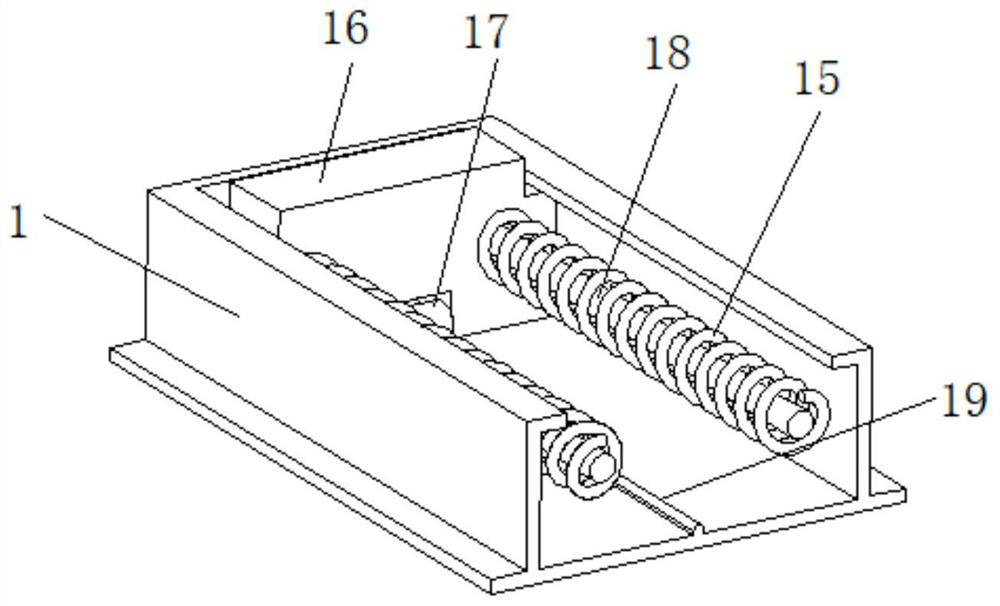
[0029] refer to Figure 1-5 , a road width limiting device, comprising a base 1 and a housing 14, a top box 8 is fixedly installed on the top of the housing 14, and two installation grooves are opened on both sides of the housing 14, and the inside of the installation groove is fixedly installed The limit sleeve 3, the top of the base 1 is provided with a chute, and the inside of the chute is slidably installed with a buffer mechanism, the housing 14 is fixedly installed on the top of the buffer mechanism, and the inside of the limit sleeve 3 is plugged with a telescopic Rod 6, and the connecting frame 5 of U-shaped structure is fixedly installed between one end of adjacent two expansion rods 6, and the outside of connecting frame 5 is fixedly installed limited width plate mechanism 2, and the inside of housing 14 is fixedly installed with two Support plate 13, and four ball nuts 11 are installed by bearing between two support plates 13, the other end of four expansion rods 6 ...

Embodiment 2

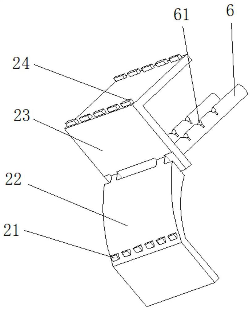
[0040] refer to Figure 1-5 , a road width limiting device. Compared with Embodiment 1 in this embodiment, the top of the top box 8 is fixedly installed with a solar panel 20, and the inside of the top box 8 is fixedly installed with a solar panel 20 electrically connected The battery pack and the time controller, the inside of the first contour reflective light 24 and the second contour reflective light 21 are fixedly installed with LED beads electrically connected to the battery pack and the time controller.

[0041] In this embodiment, when the device is in use, the setting of the time controller can be used to illuminate the first contour reflective light 24 and the second contour reflective light 21 at night through the LED lamp beads, so as to increase the clarity of the outline of the device and make it more transparent. It is beneficial for passing vehicles and pedestrians to observe the position of the device, and further improves the alert effect on night driving and...


PUM


Abstract

The invention discloses a width limiting device for roads, and relates to the technical field of road construction. The problem that the width limiting distance is not easy to adjust after a width limiting pier of a road is placed is solved. The device specifically comprises a base and a shell, a top box is fixedly mounted at the top end of the shell, two mounting grooves are formed in the two sides of the shell, limiting sleeves are fixedly mounted in the mounting grooves, a sliding groove part is formed in the top end of the base, a buffer mechanism is slidably mounted in the sliding groovepart, and the shell is fixedly mounted at the top end of the buffer mechanism; and telescopic rods are inserted into the limiting sleeves. The width limiting part is mainly composed of the width limiting plate mechanisms on the two sides, so that the phenomenon that rearview mirrors are scratched and damaged when cars and other vehicles pass can be avoided; and meanwhile, when the vehicles directly impact the surface of the device, the buffering mechanism in the device works to drive the upper portion of the device to retreat, so that impact on the vehicle is buffered, and the damage degree ofthe collided vehicle is reduced.

Description

technical field [0001] The invention relates to the technical field of road construction, in particular to a road width limiting device. Background technique [0002] Urban roads lead to all areas of the city, used for transportation and pedestrians in the city, convenient for residents to live, work and cultural and entertainment activities, and connect with roads outside the city that bear the burden of external traffic. Urban roads are generally wider than highways. To adapt to complex The transportation means are divided into motor vehicle lanes, bus priority lanes, non-motor vehicle lanes, etc. On both sides of the road, there are sidewalks and housing buildings above the road surface, and public pipelines are mostly buried under the sidewalks. Arrange green belts and sculptures to beautify the city. In order to protect the sanitation of the urban environment, it is necessary to reduce dust and noise. [0003] At many newly constructed road intersections, width-limit...

Claims


Application Information

Patent Timeline
Patent Type & Authority Applications(China)
IPC IPC(8): E01F13/00
CPCE01F13/00
Inventor 李好宣
Owner 李好宣
Learn More