Rolling gate control device

A control device and technology for rolling gates, applied in the field of rolling gates, can solve problems such as motor and door panel damage, reduced sealing, door panel and door panel limit frame deviation, etc., to improve service life, prevent jamming damage, and improve sealing sexual effect

Pending Publication Date: 2021-01-29
湛江市安信门业有限公司
View PDF0 Cites 0 Cited by
  • Summary
  • Abstract
  • Description
  • Claims
  • Application Information

AI Technical Summary

Problems solved by technology

[0005] With the improvement of people's living standards and the requirements for convenience, more and more electric rolling gates are used. The electric rolling gates of the existing products mainly include: motor, sprocket, door curtain reel, door panel, sprocket and door curtain The reel is fixedly connected. When the door is opened and closed by a button or a remote control device, the motor rotates, and the output shaft of the motor drives the sprocket to rotate synchronously through the chain. The sprocket drives the door curtain reel to rotate synchronously to roll up or down the door. Or when it is fully open, it will touch the limit switch to stop the motor rotation. Since the electric rolling gate drive motor is equipped with a brake device, when the operation is completed or the power is cut off, the motor brake system will make the motor output shaft in the braking state, and the sprocket and the curtain will be in a braking state. Therefore, the reel is locked and the door cannot be opened and closed;
[0006] When the existing electric rolling door is working, when the door curtain reel rotates to rewind the door panel, the door curtain reel cannot follow the thickness of the rewinding, because the greater the rewinding thickness, the deviation between the door panel and the limit frame of the door panel will occur, resulting in There is friction between the door panel and the limit frame of the door panel, which will cause greater wear and greater noise when rising;
[0007] When falling, the door panel and the top of the limit frame of the door panel are easy to get stuck, causing the door panel to fail to fall stably, and it is easy to cause damage to the motor and door panel. The gap between the door panel and the inner wall of the door panel limit frame increases, which reduces the sealing performance. We propose a rolling gate control device

Method used


Image

  • Rolling gate control device
  • Rolling gate control device
  • Rolling gate control device

Examples


Embodiment Construction

[0026] The following will clearly and completely describe the technical solutions in the embodiments of the present invention with reference to the accompanying drawings in the embodiments of the present invention. Obviously, the described embodiments are only some, not all, embodiments of the present invention. Based on the embodiments of the present invention, all other embodiments obtained by persons of ordinary skill in the art without making creative efforts belong to the protection scope of the present invention.

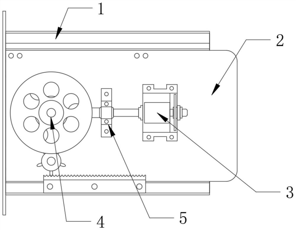
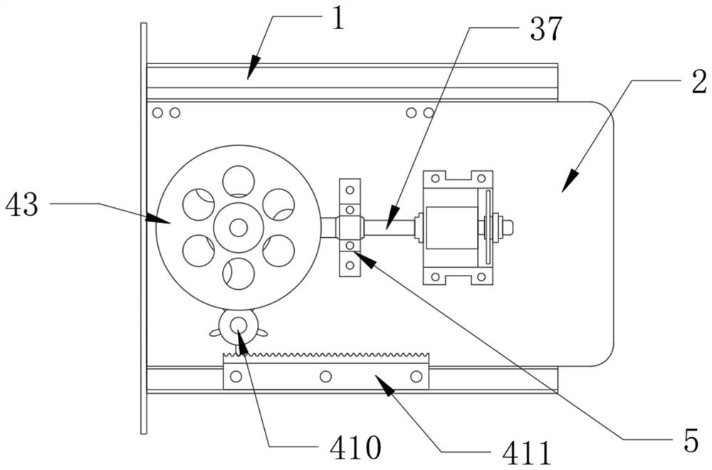
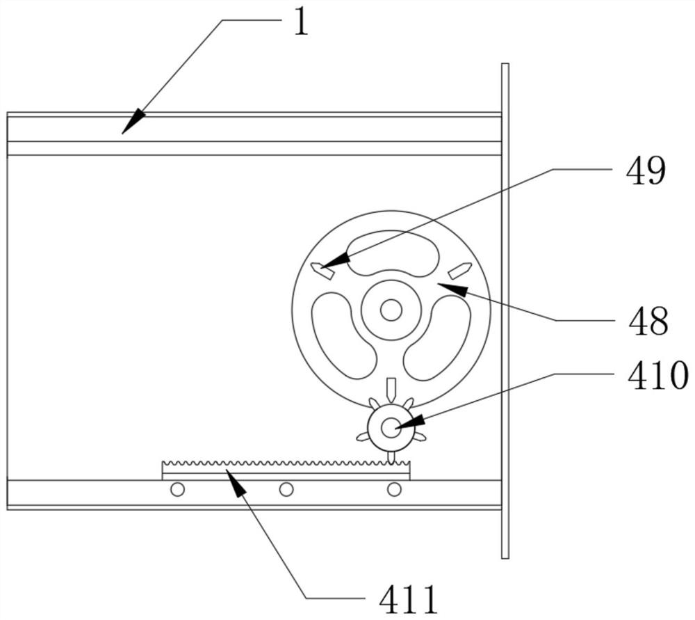
[0027] see figure 1 , a control device for a rolling gate in the illustration, including a side plate frame 1 and a side plate 2, one side of the side plate frame 1 is slidably connected to the side plate 2 through a guide rail, and one side of the side plate 2 is fixed with a bolt The transmission clutch 3, the side plate 2 close to the transmission clutch 3 is equipped with a follow-up mechanism 4 for stable transmission, and the output end of the transmissi...


PUM


Abstract

The invention discloses a rolling gate control device. The rolling gate control device comprises a side plate frame and a side plate; one side of the side plate frame is slidably connected with the side plate through a guide rail; a transmission clutch is fixed to one side of the side plate through a bolt; a follow-up mechanism for stable transmission is installed on the side, close to the transmission clutch, of the side plate; and the output end of the transmission clutch is connected with the input end of the follow-up mechanism. According to the rolling gate control device, driving of a motor can be clutched through the transmission clutch, the situation that a door plate cannot be opened or closed during power failure or motor damage is prevented, following can be conducted along withthe rolling thickness of the door plate through the follow-up mechanism when the door plate is rolled, noise can be greatly reduced, the sealing performance is improved, the door plate is prevented from being stuck and damaged, the service life is prolonged, people can conveniently adjust the door according to doors with different heights, and people can conveniently use the door.

Description

technical field [0001] The invention relates to the technical field of rolling gates, in particular to a rolling gate control device. Background technique [0002] Rolling gate, also known as "rolling shutter door", is connected in series with many joint movable doors. In a fixed slideway, the upper and lower doors are rotated around the reel above the door. The rolling mode of the rolling gate is divided into manual and electric. way; [0003] Manual mode: With the help of the balance force of the torsion spring on the central shaft of the roller blind, the roller shutter switch can be easily pulled up and down manually; [0004] Electric mode: Use a special motor to drive the central shaft of the roller blind to rotate to reach the roller shutter switch, and stop automatically when the rotation reaches the upper and lower limits set by the motor; [0005] With the improvement of people's living standards and the requirements for convenience, more and more electric rollin...

Claims


Application Information

Patent Timeline
Patent Type & Authority Applications(China)
IPC IPC(8): E06B9/68E06B9/56H02K7/102F16D27/108F16D27/118F16D27/14F16H19/04
CPCE06B9/56E06B9/68F16D27/108F16D27/118F16D27/14F16D2027/008F16H19/04H02K7/1023
Inventor 吴诗舜邱振东陈伟
Owner 湛江市安信门业有限公司
Why Eureka
Try Eureka