Automatic LED lamp holder production method

An automatic production method and the technology of LED lamp caps, which are applied in the direction of lighting and heating equipment, semiconductor devices of light-emitting elements, manufacturing tools, etc., can solve problems such as low installation efficiency, scrapped lamp caps, and separation of LED lamp beads, so as to improve production efficiency, The effect of ensuring production quality

Inactive Publication Date: 2021-01-29
肖永生
View PDF0 Cites 11 Cited by
  • Summary
  • Abstract
  • Description
  • Claims
  • Application Information

AI Technical Summary

Problems solved by technology

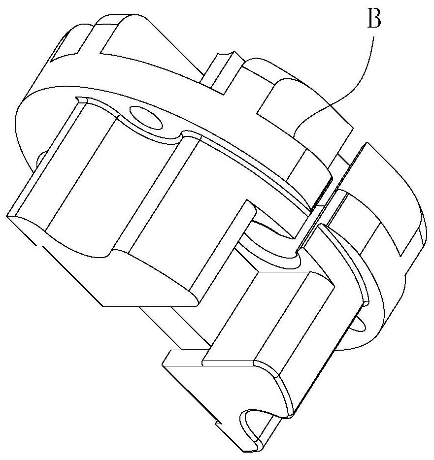
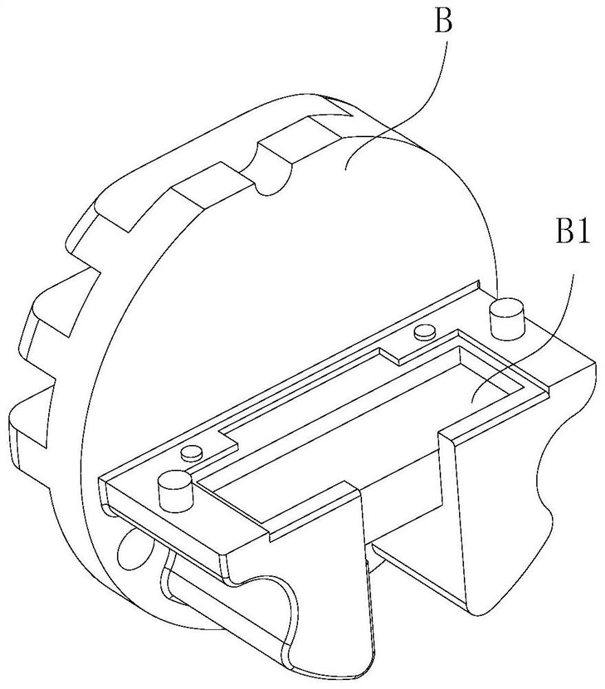
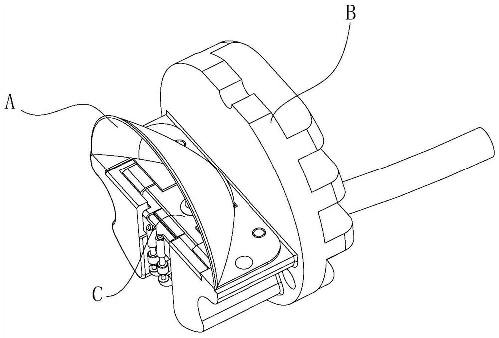
[0002] In actual application of vehicle lamp caps, lenses are generally installed outside the LED lamp beads to enhance the brightness of the LED lamp caps and achieve the effect of concentrating light, so that the LED lamp caps can have higher penetration. Combined with the attached drawings, the actual assembly At this time, the LED lamp bead is fixed on the heat sink B through the reflective bowl A, and the card slot B1 for the LED lamp bead is arranged on the heat sink B, and the reflective bowl A is also fixed on the heat sink B by screws, and the lead wire of the LED lamp C goes through Through the through hole on the heat sink, after the LED lamp cap and the heat sink B are installed, guide the heat sink B into the lamp tube D of the lamp cap, so as to realize the connection between the heat sink B and the lamp D, and the nozzle of the lamp D Lens is set at the end to form the final LED lamp holder. In the actual use process, the LED lamp holder can be installed in the vehicle headlight. In the actual assembly process of the above-mentioned LED lamps, manual methods are mostly used, resulting in installation efficiency. When the lead wire of the LED lamp bead passes through the through hole on the heat sink B, if the lead wire is pulled by external force, it is easy to cause the separation of the LED lamp bead C and the lead wire, thus causing the lamp holder to be scrapped

Method used


Image

  • Automatic LED lamp holder production method
  • Automatic LED lamp holder production method
  • Automatic LED lamp holder production method

Examples


Embodiment Construction

[0057] In order to make the objects and advantages of the present invention clearer, the present invention will be described in detail below in conjunction with the examples. It should be understood that the following words are only used to describe one or several specific implementation modes of the present invention, and do not strictly limit the protection scope of the specific claims of the present invention. As used herein, the terms "parallel" and "perpendicular" are not limited to their strict geometric definitions, but include reasonable and inconsistent tolerances for machining or human error;

[0058] The specific features of the LED lamp cap automatic production system are described in detail below:

[0059] An automatic production system for LED lamp caps, comprising a cooling base feeding device 10, a reflective bowl feeding device 20 and an LED lamp bead feeding device 30, the cooling base feeding device 10 is used to lead out the cooling base, and the reflective...


PUM


Abstract

The invention relates to an automatic LED lamp holder production method. The method comprises the steps that a heat dissipation base is led out to the outlet position of a heat dissipation base feeding device; a reflecting bowl is led out to the outlet position of a second leading-out rail of a reflecting bowl feeding device; LED lamp beads are led out to the positions of clamping blocks; a bottomcover is led out into a feeding pipe of a bottom cover feeding device; a lamp tube is led out to a lamp tube feeding channel of a lamp tube feeding device; a glue solution is extruded into a mountinggroove of the heat dissipation base; an LED lamp wick is pushed into the mounting groove of the heat dissipation base; the reflecting bowl is pushed to the position of the mounting face of the heat dissipation base; the bottom cover abuts against one end of the heat dissipation base and is integrally installed with the heat dissipation base; a wire is clamped in a notch of the heat dissipation base and an opening of the bottom cover, and clamping of the wire is achieved; and the heat dissipation base is inserted into the lamp tube, and installation operation of the heat dissipation base and the lamp tube is realized. By means of the method, the production efficiency of the LED lamp holder can be improved, meanwhile, the LED lamp wick is protected, and the production quality of the lamp holder is guaranteed.

Description

technical field [0001] The invention relates to the technical field of LED lamp assembly, in particular to an automatic production method for LED lamp holders. Background technique [0002] In actual application of vehicle lamp caps, lenses are generally installed outside the LED lamp beads to enhance the brightness of the LED lamp caps and achieve the effect of concentrating light, so that the LED lamp caps can have higher penetration. Combined with the attached drawings, the actual assembly At this time, the LED lamp bead is fixed on the heat sink B through the reflective bowl A, and the card slot B1 for the LED lamp bead is arranged on the heat sink B, and the reflective bowl A is also fixed on the heat sink B by screws, and the lead wire of the LED lamp C goes through Through the through hole on the heat sink, after the LED lamp cap and the heat sink B are installed, guide the heat sink B into the lamp tube D of the lamp cap, so as to realize the connection between the h...

Claims


Application Information

Patent Timeline
Patent Type & Authority Applications(China)
IPC IPC(8): F21K9/90F21Y115/10
CPCF21K9/90F21Y2115/10F21V29/70F21S4/28B23P19/04F21V17/101F21V23/001B23P21/004B23P21/008
Inventor 肖永生肖振张政
Owner 肖永生
Why Eureka
Try Eureka