

A microwave induction warning device
An alarm device and microwave induction technology, applied in alarms, anti-theft alarms, instruments, etc., can solve the problems of complex and changeable monitoring equipment environment and large demand, and achieve simple installation, high sensitivity, and wide sensing range Effect
- Summary
- Abstract
- Description
- Claims
- Application Information
AI Technical Summary
Problems solved by technology
Method used
Image

Examples
Embodiment 1
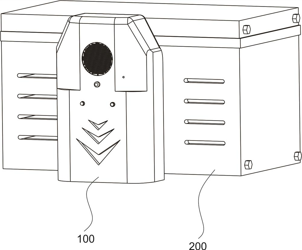
[0031] refer to figure 1 , as the first embodiment of the present invention, a microwave induction alarm device is provided. The sliding part 102 , the warning part 103 and the alarm part 104 arranged in the alarm 101 ; the base 200 includes a placement box 201 and a reminder part 202 arranged in the placement box 201 .
[0032] Among them, the alarm component 100 constitutes the main functional parts of the microwave induction alarm device, which is used to give early warning to nearby personnel. If it is detected, activate the sound and light alarm, and issue warning language, such as: high voltage danger, please do not approach or someone is working, prohibit closing, etc., and at the same time issue a flashing alarm light to improve night visibility. The sliding part 102 is used to sense the state of the alarm 101. When the alarm 101 is connected to the base 200, it is in a normal working state. The sliding part 102 is lifted. When the alarm 101 falls or is taken off, Th...
Embodiment 2
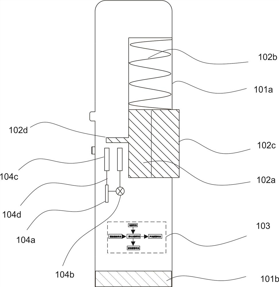
[0036] refer to figure 2 , 3 , which is the second embodiment of the present invention. This embodiment is different from the first embodiment in that: a sliding groove 101a is provided on the rear wall of the alarm 101, and the sliding groove 101a is a rectangular parallelepiped, and a sliding part 102 is provided inside it. , the bottom of the alarm 101 is also fixedly provided with a bearing block 101b.
[0037] The slider 102 includes a limiting plate 102a, a spring 102b arranged between the limiting plate 102a and the inner wall of the sliding groove 101a, a magnet block 102c fixedly connected with the limiting plate 102a, and the opposite side of the limiting plate 102a and the installation magnet block 102c A first iron block 102d is fixedly arranged on the top.
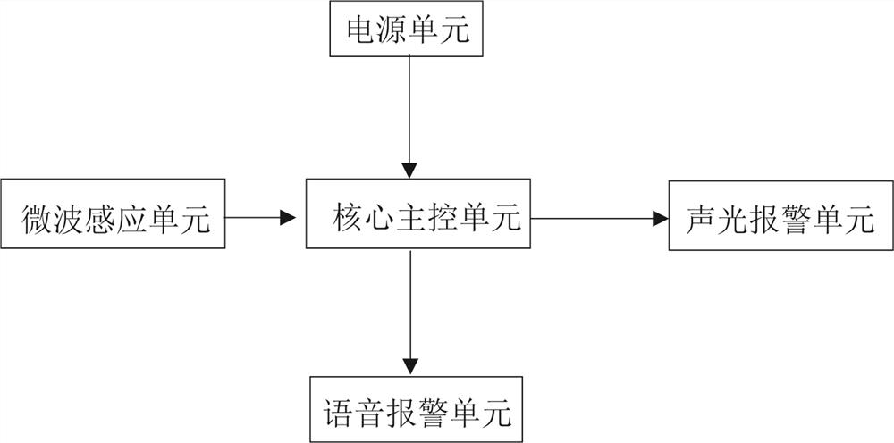
[0038] The early warning device 103 includes a core main control unit 103a, a power supply unit 103b, a microwave induction unit 103c, a voice alarm unit 103d, and an audible and visual alarm unit 103e, and...
Embodiment 3
[0043] refer to Figure 4 , 5 , is the third embodiment of the present invention, and this embodiment is different from the second embodiment in that: a through hole 201a is opened on the surface of the placement box 201, and the reminder 202 is arranged in the through hole 201a, and the placement box 201 is also provided with a There is a pressure chamber 201b, and a limiting groove 201a-1 is provided on the side of the pressure chamber 201b close to the through hole 201a, and the axial cross section of the limiting groove 201a-1 is triangular.
[0044] Prompt 202 comprises the delay relay 202a that is fixedly arranged on the inner wall of setting box 201, power supply module 202b, loudspeaker 202c and the second contact iron block 104c-1, wherein all units are connected in series by the 3rd electric wire 202d, the 3rd electric wire 202d two A second contact iron block 104c-1 is connected to the terminal.
[0045] The prompting piece 202 also includes a compression piece 20...
PUM
 Abstract
Description
Claims
Application Information