Folding antenna mounting frame for erecting shore-based antenna of unmanned ship

A technology for mounting racks and unmanned boats, which is applied in the directions of antenna supports/installation devices, antennas, and rotating antennas. The effects of transportation, reduced space occupation, and convenient erection

Active Publication Date: 2021-01-29
TIANJIN NAVIGATION INSTR RES INST
View PDF7 Cites 0 Cited by
  • Summary
  • Abstract
  • Description
  • Claims
  • Application Information

AI Technical Summary

Problems solved by technology

[0003] At present, the erection of shore-based antennas mostly relies on communication vehicles, shelters or self-made fixed antenna racks. In use, there are mainly disadvantages such as transportation difficulties, multi-person cooperation required for erection, high environmental requirements for erection, and a small number of antennas for erection.

Method used


Image

  • Folding antenna mounting frame for erecting shore-based antenna of unmanned ship
  • Folding antenna mounting frame for erecting shore-based antenna of unmanned ship
  • Folding antenna mounting frame for erecting shore-based antenna of unmanned ship

Examples


Embodiment Construction

[0027] The present invention will be further described in detail below in conjunction with the accompanying drawings and through specific embodiments. The following embodiments are only descriptive, not restrictive, and cannot limit the protection scope of the present invention.

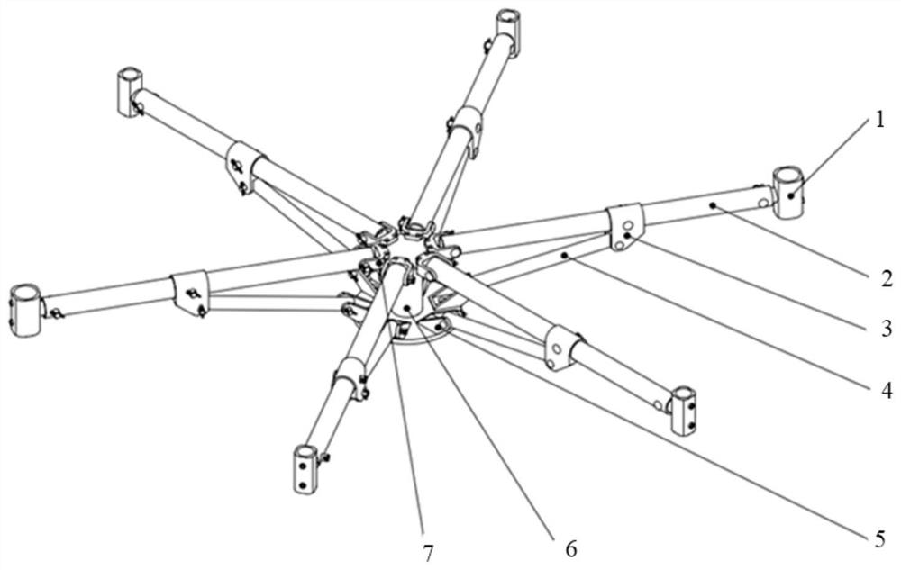
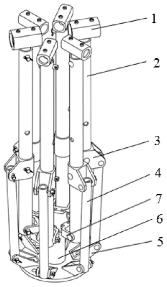
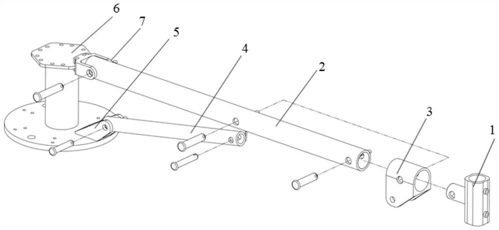
[0028] A kind of foldable antenna mounting frame for unmanned ship shore-based antenna erection, please refer to Figure 1-9 , and its invention points are: including a central base 6, a plurality of antenna fixing rods 2, a plurality of antenna mounting sleeves 1, a plurality of fixing rod mounting bases 7, a plurality of antenna support rods 4, a plurality of connecting parts 3 between rods and A plurality of support rods are installed with the base 5 .

[0029] Center base:

[0030] The center base is composed of an upper installation platform 6.1, a lower installation platform 6.3 and a central column 6.2 connecting the two installation platforms. Reserve 3 evenly distributed installation holes...


PUM


Abstract

The invention relates to a foldable antenna mounting frame for erecting a shore-based antenna of an unmanned ship. The foldable antenna mounting frame is characterized in that: inner ends of a plurality of antenna fixing rods are respectively hinged with an upper mounting table of a central base through a plurality of fixing rod mounting bases; the outer ends of the plurality of antenna fixing rods are fixedly connected with a plurality of antenna mounting sleeves respectively; the inner ends of a plurality of antenna support rods are respectively hinged with the lower mounting table of the central base through a plurality of support rod mounting bases; the outer ends of the plurality of antenna supporting rods are respectively hinged with a plurality of inter-rod connecting pieces, and the plurality of inter-rod connecting pieces are respectively sleeved on the plurality of antenna fixing rods in a sliding manner; an inner pin hole is formed in the middle of each antenna fixing rod, and an outer pin hole is formed in each inter-rod connecting piece; when the plurality of antenna fixing rods are unfolded to a horizontal position, the inner and outer pin holes are aligned, and the positioning pins are inserted, so that the whole antenna mounting frame is in an unfolded and erected state; and when the plurality of antenna fixing rods rotate to the vertical positions around the hinge points, the antenna mounting frame is integrally in a folded state. The shore-based antenna can be rapidly and conveniently erected and is convenient to store and transport.

Description

technical field [0001] The invention belongs to the technical field of unmanned boat shore-based antenna erection, and in particular relates to a foldable antenna mounting frame for unmanned boat shore-based antenna erection. Background technique [0002] An unmanned surface ship is an unmanned surface ship, which is mainly used to perform dangerous and unsuitable tasks for manned ships. Once it is equipped with advanced control systems, sensor systems, communication systems and weapon systems, it can carry out a variety of warfare and non-combat military missions. The shore-based antenna is an important physical support in the communication system of the unmanned ship. The number, height and installation distance between the antennas have a great impact on the communication effect. In addition, as a mobile information and communication platform, the shore-based antenna for unmanned boats has high requirements for its transportability and installation. [0003] At present,...

Claims


Application Information

Patent Timeline
IPC IPC(8): H01Q1/12H01Q1/08
CPCH01Q1/1235H01Q1/084
Inventor 王喆高志宇米洋徐晓茹
Owner TIANJIN NAVIGATION INSTR RES INST
Why Eureka
Try Eureka