
Pixel circuit of infrared detector and driving method

An infrared detector and pixel circuit technology, applied in the field of infrared detectors, can solve problems such as small integral voltage and signal truncation, and achieve the effect of eliminating thermal noise and improving readout capability.

Pending Publication Date: 2021-01-29
HUAZHONG UNIV OF SCI & TECH
View PDF0 Cites 0 Cited by
  • Summary
  • Abstract
  • Description
  • Claims
  • Application Information

AI Technical Summary

Problems solved by technology

[0005] Aiming at the defects and improvement needs of the prior art, the present invention provides an infrared detector pixel circuit and a driving method, the purpose of which is to realize real correlated double sampling, eliminate the thermal noise introduced in the reset process, and solve the problem of under-light conditions. The problem that the signal is truncated due to the small integral voltage of the pixel, and at the same time reduce the 1 / f noise of the pixel point circuit

Method used


Image

  • Pixel circuit of infrared detector and driving method
  • Pixel circuit of infrared detector and driving method
  • Pixel circuit of infrared detector and driving method

Examples


Embodiment Construction

[0029] In order to make the object, technical solution and advantages of the present invention clearer, the present invention will be further described in detail below in conjunction with the accompanying drawings and embodiments. It should be understood that the specific embodiments described here are only used to explain the present invention, not to limit the present invention. In addition, the technical features involved in the various embodiments of the present invention described below can be combined with each other as long as they do not constitute a conflict with each other.

[0030] In the present invention, the terms "first", "second" and the like (if any) in the present invention and drawings are used to distinguish similar objects, and are not necessarily used to describe a specific order or sequence.

[0031] In order to eliminate the thermal noise of the pixel circuit, improve the readout ability of the circuit for weak light signals, reduce the 1 / f noise of the...


PUM


Abstract

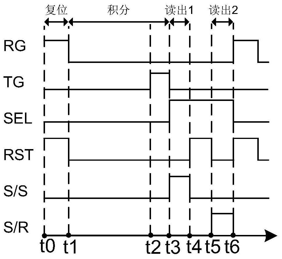
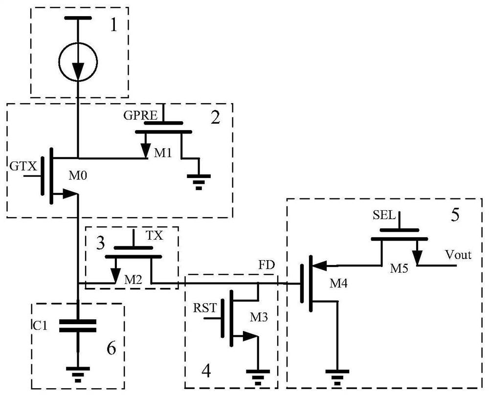
The invention discloses a pixel circuit of an infrared detector and a driving method, and belongs to the field of infrared detector circuit design. The pixel circuit comprises an integral control circuit, a signal transmission circuit, a reset circuit, a gating read-out circuit and an integral capacitor. According to the pixel circuit of the infrared detector and the driving method provided by theinvention, the reset voltage and the signal voltage can be read out in a time-sharing manner in a short time interval of the same frame, and thermal noise signals contained in two times of sampling in the short time interval of the same frame are also basically the same, so the difference between the two times of sampling voltages is calculated through a subsequent circuit; theoretically, the thermal noise of the pixel circuit can be completely eliminated.

Description

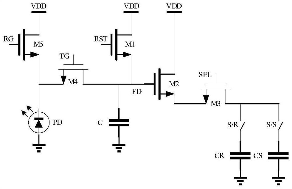
technical field [0001] The invention belongs to the technical field of infrared detectors, and more specifically relates to a pixel circuit and a driving method of an infrared detector. Background technique [0002] Generally speaking, the infrared detector is divided into an infrared sensing part and a CMOS integrated circuit part. The parameter design of the CMOS integrated circuit is inseparable from the light response of the infrared sensing part. Therefore, according to the relevant parameters such as the photoresponse of the infrared sensing part, it is very important to design a dedicated CMOS integrated circuit for the construction of an infrared detector. And with the development of the times, many military and civilian application scenarios of infrared detectors require detectors to detect very weak infrared light, so how to read infrared sensing signals under weak light is a new challenge. [0003] figure 1 It is a schematic structural diagram of an existing in...

Claims


Application Information

Patent Timeline
IPC IPC(8): H03K17/30
CPCH03K17/302
Inventor 刘冬生聂正唐江高亮李豪刘婧金子睿
Owner HUAZHONG UNIV OF SCI & TECH
Learn More