Hydropower station monitoring system screen cabinet and using method thereof
A technology for monitoring systems and hydropower stations, which is applied to electrical equipment enclosures/cabinets/drawers, electrical components, electrical equipment structural parts, etc. Convenience, easy installation, and the effect of improving the efficiency of heat dissipation
- Summary
- Abstract
- Description
- Claims
- Application Information
AI Technical Summary
Problems solved by technology
Method used
Image

Examples
Embodiment 1
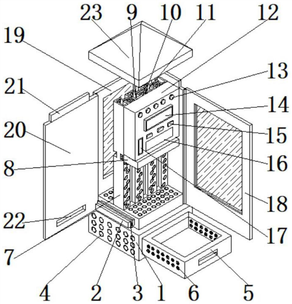
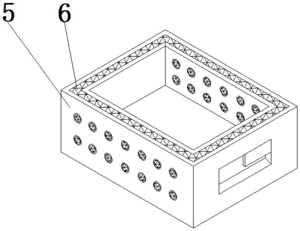
[0027] refer to Figure 1-5 , a hydropower station monitoring system screen cabinet and its use method, comprising a screen cabinet base 1, characterized in that: the top of one end of the screen cabinet base 1 is fixedly connected with a connection fixing block 2, and the outside of the middle part of the connection fixing block 2 is clamped with a fixing card Buckle 3, the bottom of one end of the screen cabinet base 1 is fixedly connected with a cooling hole 4, the bottom of the inner side of the screen cabinet base 1 is slidingly connected with a dust debris collection tank 5, and the inner wall of the dust debris collection tank 5 is clipped with a filter screen 6. The middle part of the top of the screen cabinet base 1 is fixedly connected with the installation plate 7, and the middle part on one side of the installation plate 7 is slidably connected with a fixed partition 8, and the inner side of the installation plate 7 is fixedly connected with a cooling cavity 9, and ...
Embodiment 2
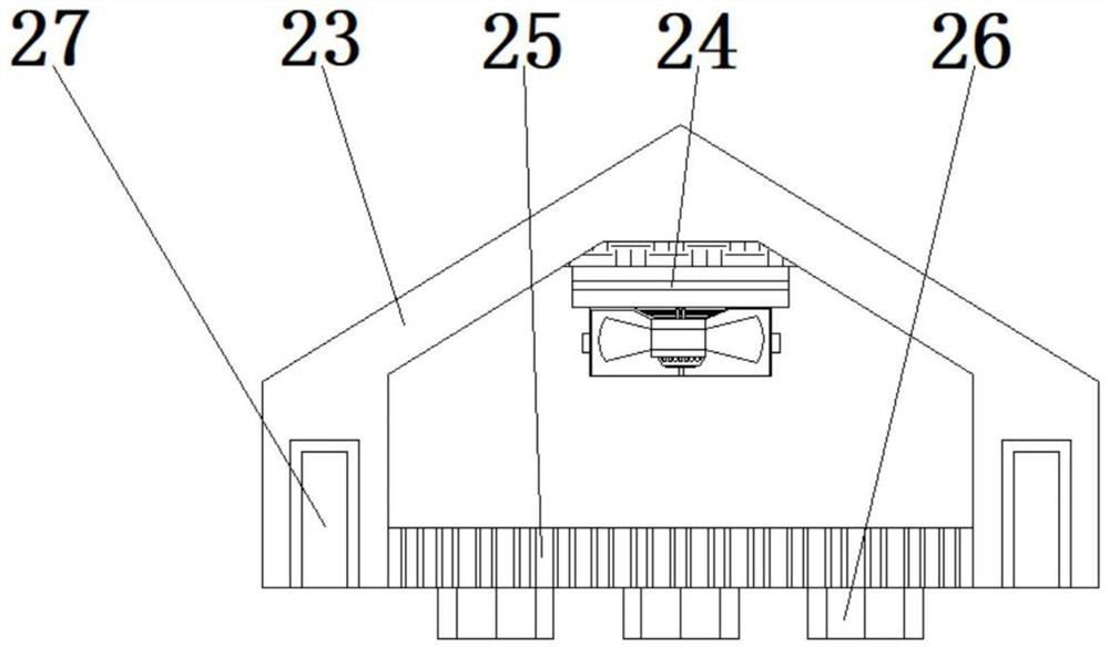
[0030] see figure 1 and image 3 , the top of one side of the monitoring system equipment 12 is fixedly connected with an indicator light 13, the bottom end of the indicator light 13 is provided with a data display screen 14, the bottom end of the data display screen 14 is provided with a control switch 15, and the bottom end of the control switch 15 is provided with Operate the touch screen panel 16, the size of the inner side of the connecting groove 22 matches the size of the outer side of the connecting fixed block 2, the size of the inner side of the first tenon groove 10 matches the size of the outer side of the first tenon 11, and the size of the outer side of the installation block 21 matches The size of the inside of the installation slot 27 matches.
[0031]In this embodiment: by setting the installation card slot 27, the installation card block 21, the connection groove 22 and the connection and fixing block 2, during installation, the connection groove 22 fixed at...
Embodiment 3
[0033] see figure 1 , figure 2 and image 3 , the top of the screen cabinet base 1 is fixedly connected with a bottom circulation cooling hole, the mounting plate 7, and one end of the dust and debris collection tank 5 is fixedly connected with a filter hole, and the middle part of the front observation door 18 and the rear observation door 19 is fixedly connected with tempered glass , the fixed buckle 3 takes the central axis of the fixed buckle 3 as the axis of symmetry, and is symmetrically divided into two halves, and one side of the fixed buckle 3 that is snapped together is rotatably connected with a fixed nut.
[0034] In this embodiment: by setting the bottom circulating heat dissipation holes and filter holes, the two are matched with each other, which is conducive to the circulation and heat dissipation of the device, and is conducive to preventing dust from entering the screen cabinet.
PUM
 Abstract
Description
Claims
Application Information
 - R&D Engineer
- R&D Manager
- IP Professional
- Industry Leading Data Capabilities
- Powerful AI technology
- Patent DNA Extraction
Browse by: Latest US Patents, China's latest patents, Technical Efficacy Thesaurus, Application Domain, Technology Topic.
© 2024 PatSnap. All rights reserved.Legal|Privacy policy|Modern Slavery Act Transparency Statement|Sitemap