Turbocharger with centered guide blade ring

A technology for exhaust gas turbines and guide vanes, which is applied to gas turbine devices, machines/engines, engine components, etc., and can solve the problems of turbine housing installation costs

Pending Publication Date: 2021-01-29
IHI CHARGING SYST INT
View PDF14 Cites 0 Cited by
  • Summary
  • Abstract
  • Description
  • Claims
  • Application Information

AI Technical Summary

Problems solved by technology

Complicated installation of the turbine housing ...

Method used


Image

  • Turbocharger with centered guide blade ring
  • Turbocharger with centered guide blade ring

Examples


Embodiment Construction

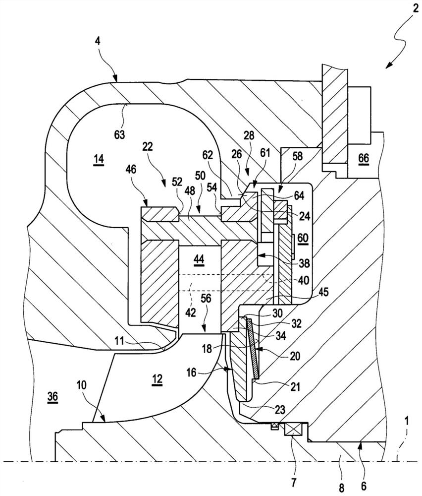
[0024] figure 1 An exhaust gas turbocharger 2 with variable turbine geometry is shown in longitudinal section along the axis of rotation 1 . The exhaust gas turbocharger 2 uses the energy of the exhaust gas to compress air and supplies the compressed air to an internal combustion engine (not shown).

[0025] The exhaust gas turbocharger 2 also has a turbine housing 4 and a bearing housing 6 fixedly connected to the turbine housing. Bearings are arranged within the bearing housing 6 for supporting the rotor shaft 8 , of which only one bearing 7 can be seen in the figure. The rotor shaft 8 is rotatable here about the axis of rotation 1 . The rotor shaft 8 is connected at its end section, not shown, in a rotationally fixed manner to the compressor wheel, and at its other end section, is formed in one piece with the turbine wheel 10 and is thus rotationally fixed. Ground is connected to the turbine wheel 10, so that the rotor shaft 8 is at the same time the turbine shaft.

[0...


PUM


Abstract

The invention relates to a turbocharger with a turbine housing (4), within which a turbine wheel (10) is arranged in a rotatable manner with respect to a rotational axis (1) and a guide blade ring (22) is arranged in a rotationally fixed manner, said guide blade ring having adjustable guide blades (44) arranged upstream of the turbine wheel (10) with respect to an exhaust gas flow. According to the invention, the guide blade ring (22) is centered with respect to the turbine housing (4) by means of a pair of support surfaces (24, 26) which are pressed against each other and at least one contactsurface (24 or 26) of which has a conical design.

Description

technical field [0001] The invention relates to an exhaust gas turbocharger of the type specified in the preamble of claim 1 . Background technique [0002] DE 10 2014 203 498 A1 shows an exhaust gas turbocharger with variable turbine geometry. The exhaust gas turbocharger has a turbine housing, within which a turbine wheel is arranged rotatably about an axis of rotation. In order to realize the variability of the turbine geometry, a guide vane ring is proposed which is also termed nozzle ring and which has adjustable guide vanes which are pivotable for this purpose. turn. Adjustable guide vanes are arranged upstream of the turbine wheel with respect to the exhaust gas flow. The guide vane ring is fixed in a rotationally fixed and radial manner relative to the turbine housing and the bearing housing. For this purpose, the guide vane ring is connected via screws to a support ring which is designed as a flat disk and is fastened between the turbine housing and the bearing ...

Claims


Application Information

Patent Timeline
IPC IPC(8): F01D17/16
CPCF01D17/165F05D2220/40F05D2250/232F05D2250/90F05D2230/64F02C6/12F05D2240/60
Inventor 马克-皮埃尔·魏斯
Owner IHI CHARGING SYST INT
Why Eureka
Try Eureka