
Bearing system of printing machine and printing machine thereof

A technology for printing machines and bearings, which is applied to printing machines, general parts of printing machinery, rotary printing machines, etc., and can solve problems such as adverse effects on printing quality and increased radial clearance

Inactive Publication Date: 2014-08-27
SCHAEFFLER TECH AG & CO KG
View PDF8 Cites 0 Cited by
  • Summary
  • Abstract
  • Description
  • Claims
  • Application Information

AI Technical Summary

Problems solved by technology

In addition, machining-induced tolerances occur which further increase the radial play
However, this bearing clearance adversely affects the printing quality

Method used


Image

  • Bearing system of printing machine and printing machine thereof

Examples


Embodiment Construction

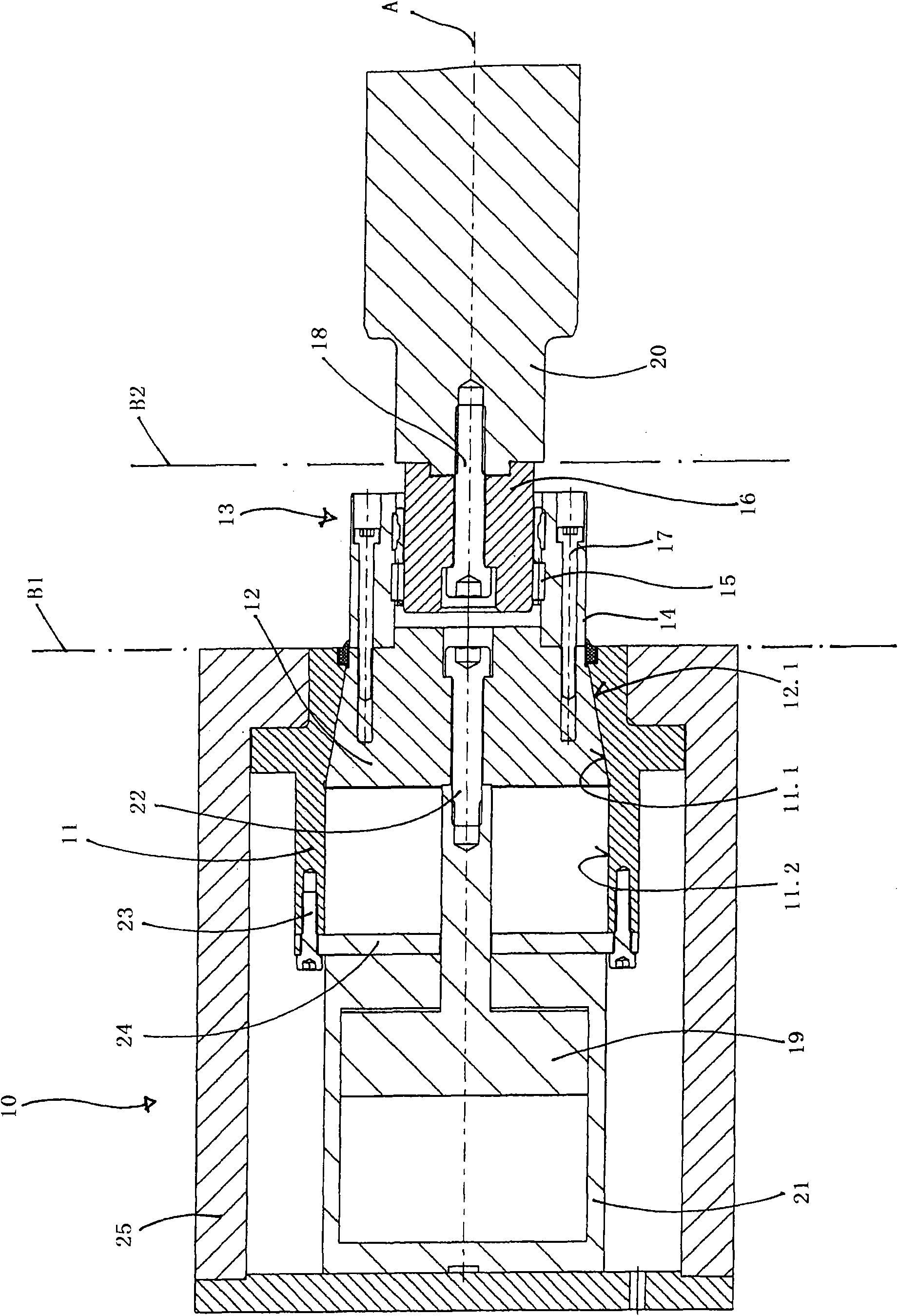
[0019] From this longitudinal section, firstly a bearing system 10 can be seen, which comprises a first housing part 11 and a second housing part 12 guided axially in the first housing part 11 . The two housing parts 11 , 12 have, corresponding to one another, conically extending circumferential regions 11 . 1 , 12 . 1 for forming the axial joint. On the conically distributed inner peripheral region 11.1 of the first housing part 11, a cylindrical inner peripheral region 11.2 is attached, which surrounds a cavity which, when a suitable force is applied, can push the second housing part 12 is pulled back into the cavity. The force is applied by means of a pneumatically actuatable piston 19 which is rigidly connected via a piston rod to the second housing part 12 and which is accommodated in a piston housing 21 which in turn is fixed to the first housing part 11 connect. Here, the piston housing has a radially protruding end plate 24 in which bores are provided for receiving f...


PUM


Abstract

The releasable and slidable bearing assembly (10) has two housing components (11,12). The former housing component is moved transverse to cylinder or roller axis. The latter housing component is arranged parallely to cylinder or roller axis in sliding manner. A roller bearing (13) is provided with force and positive-fit outer ring (14), which is connected with the latter housing component. An independent claim is also included for a printing press with roll thread.

Description

technical field [0001] The invention relates to a releasable and displaceable bearing system for supporting the free ends of cylinders or rollers on printing presses, in particular flexographic printing presses, which are supported at one end and are formed as journals. Furthermore, the invention relates to a printing machine, in particular a flexographic printing machine, having such a bearing system. Background technique [0002] On such printing presses, in particular flexographic printing presses, the image to be printed is changed by changing the printing cylinder sleeve carrying the relief plate, the so-called “sleeve”. In order to be able to change the sleeve, the respective printing cylinder or the respective roller must be freely accessible at least temporarily at one end. Therefore, such cylinders or rollers are generally supported in the air at one end. That is to say, the end of the free bearing is provided with a bearing system for accommodating the journal or...

Claims


Application Information

Patent Timeline
Patent Type & Authority Patents(China)
IPC IPC(8): B41F13/26B41F13/32B41F31/30F16C13/02
CPCB41F13/20B41F13/30B41P2213/802
Inventor 托马斯·迪滕赫费尔哈姆德·拉姆扎纳利
Owner SCHAEFFLER TECH AG & CO KG
Learn More