Three-dimensional data encoding method, three-dimensional data decoding method, three-dimensional data encoding device, and three-dimensional data decoding device

A technology of three-dimensional data and decoding method, applied in the field of three-dimensional data encoding, three-dimensional data decoding, three-dimensional data encoding device, and three-dimensional data decoding device, can solve the problem of large amount of point group data, etc., and achieve the effect of shortening the processing time

Pending Publication Date: 2021-01-29
PANASONIC INTELLECTUAL PROPERTY CORP OF AMERICA
1 Cites 0 Cited by

AI-Extracted Technical Summary

Problems solved by technology

Although it is expected that point cloud will become the mainstream as a re...

Method used

In addition, as described above, by adding the number NumOfPoint of the three-dimensional points of each hierarchy to the header and the like, the three-dimensional data decoding device can perform LoD generation processing (S3311) and arithmetic decoding processing of n-bit encoding and residual encoding ( S3318A) Independent. Therefore, as shown in FIG. 93 , the three-dimensional data decoding device may perform LoD generation processing ( S3311 ) and arithmetic decoding processing ( S3318A) in parallel. Thereby, the overall processing time can be reduced.
In this way, the inter prediction unit 1311 applies rotation and translation processing to the reference space so that the overall positional relationship between the encoding target space and the reference space is approximated, and then generates a prediction volume using information in the reference space. In this way, The accuracy of the predicted volume can be improved. Furthermore, since the prediction residual can be suppressed, the amount of coding can be reduced. In addition, although an example of performing ICP using the coding target space and the reference space is shown here, the present invention is not limited thereto. For example, in order to reduce the amount of processing, the inter prediction unit 1311 may perform ICP using at least one of the encoding target space in which voxels or point cloud numbers are extracted, and the reference space in which voxel or point cloud numbers are extracted, to obtain RT information.
Thus, the three-dimensional data encoding device can improve encoding efficiency by referring to the information of the first node whose parent node is the same as the parent node of the object node among a plurality of adjacent nodes spatially adjacent to the object node. . In addition, since the three-dimensional data encoding device does not refer to information of a second node whose parent node is different from that of the target node among a plurality of adjacent nodes, the processing amount can be reduced. In this way, the three-dimensional data encoding device can improve encoding efficiency and reduce processing load.
[0121] Thus, the three-dimensional data decoding method can shorten the processing time by performing parallel processing on a part of the processing.
[0149] Furthermore, in the configuration shown in FIG. 3 , the encoding device or the decoding device sequentially encodes or decodes a plurality of layers starting from the lower layer (layer 1). Accordingly, for example, for an autonomous vehicle or the like, it is possible to increase the priority of data near the ground with a large amount of information.
[0228] Furthermore, the space or volume includes a feature point group derived from information obtained by a sensor such as a depth sensor, a gyroscope, or a camera. The coordinates of the feature points are set as the center positions of the voxels. In addition, by subdividing voxels, it is possible to achieve high accuracy of position information.
[0255] In an application that utilizes feature data for a certain purpose, by using SWLD information instead of WLD, it is possible to reduce the read time from the hard disk, and to reduce the frequency band and transmission time during network transmission. For example, WLD and SWLD are stored in the server in advance as map information, and the network bandwidth and transmission time can be suppressed by switching the map information to be sent to WLD or SWLD according to the request from the client. Specific examples are shown below.
[0267] In addition, the server may create SWLD for each object based on WLD, and the client may receive SWLD according to usage. According to this, the network bandwidth can be suppressed. For example, the server pre-identifies a person or a vehicle from the WLD, and creates a person's SWLD and a vehicle's SWLD. The client receives the SWLD of the person when it wants to acquire the information of the people around it, and receives the SWLD of the car when it wants to acquire the information of the car. Also, the type of this SWLD can be distinguished by information (flag, type, etc.) added to the header.
[0281] For example, the SWLD extraction unit 403 regenerates the extracted three-dimensional data 412 with a reduced number of extracted feature points, and the SWLD encoding unit 405 encodes the extracted three-dimensional data 412. Alternatively, the degree of quantization in the SWLD encoding unit 405 may be coarsened. For example, in an octree structure described later, the degree of quantization can be made rough by rounding the data at the lowest layer.
[0295] Also, in general, it is difficult to include VXL data of flat regions in SWLD. For this purpose, the server holds a downsampled world space (SubWLD) in which the WLD is downsampled for detection of stationary obstacles, and may transmit the SWLD and the SubWLD to the client. Accordingly, the network bandwidth can be suppressed, and self-position estimation and obstacle detection can be performed on the client side.
[0330] Accordingly, the 3D data decoding apparatus 500 can increase the priority of inter prediction for extracting 3D data whose correlation between adjacent data tends to be low.
[0393] The format conversion unit 821 generates the three-dimensional data 837 by converting the three-dimensional data 836 in the transmission area among the three-dimensional data 835 stored in the three-dimensional data storage unit 818 into a format corresponding to the receiving side. In addition, the format conversion unit 821 may compress or encode the three-dimensional data 837 to reduce the amount of data.
[0423] The format conversion unit 1019 generates sensor information 1037 by converting the sensor information 1033 into a format corresponding to the receiving side. In addition, the format conversion unit 1019 can reduce the amount of data by compressing or encoding the sensor information 1037 . Also, when format conversion is not required, the format conversion unit 1019 can omit the processing. Furthermore, the format conversion unit 1019 can control the amount of data to be transmitted according to the designation of the transmission range.
[0436] The format conversion unit 1119 generates the three-dimensional map 1031 by converting the three-dimensional map 1135 into a format corresponding to the receiving side. In addition, the format conversion unit 1119 may also compress or encode the 3D map 1135 to reduce the amount of data. Furthermore, when format conversion is unnecessary, the format conversion unit 1119 may omit the processing. Furthermore, the format conversion unit 1119 can control the amount of data to be transmitted according to the designation of the transmission range.
[0456] The client device 902 includes a three-dimensional map decoding processing unit 1211 and a sensor information compression processing unit 1212. The 3D map decoding processing unit 1211 receives the compressed encoded data of the 3D map, decodes the encoded data, and obtains the 3D map. The sensor information compression processing unit 1212 does not compress the three-dimensional data created from the obtained sensor information, but compresses the sensor information itself, and transmits the encoded data of the compressed sensor information to the server 901 . According to this configuration, the client device 902 can internally store a processing unit (device or LSI) for decoding a three-dimensional map (point cloud, etc.) without storing a three-dimensional map (point cloud, etc.) The processing section for compressing data is kept inside. In this way, the cost, power consumption, and the like of the client device 902 can be suppressed.
[0462] Furthermore, the client device 902 encodes or compresses the sensor information 1033, and transmits the encoded or compressed sensor information 1037 to the server 901 or another mobile body 902 during the transmission of the sensor information. Accordingly, the client device 902 can reduce the amount of data transmitted.
[0465] Accordingly, the server 901 creates three-dimensional data 1134 using the sensor information 1037 transmitted from the client device 902. In this way, compared with the case where the client device 902 transmits three-dimensional data, there is a possibility that the data amount of transmission data can be reduced. In addition, since the client device 902 does not need to perform processing such as compression or encoding of the three-dimensional data, the processing amount of the client device 902 can be reduced. In this way, the server 901 can reduce the amount of data to be transmitted or simplify the configuration of the device.
[0470] Moreover, the server 901 further corrects the three-dimensional data according to the performance of the sensor. Accordingly, the three-dimensional data creation method can improve the quality of the three-dimensional data.
[0472] Furthermore, the server 901 decodes or decompresses the received sensor information 1037, and creates three-dimensional data 1134 based on the decoded or decompressed sensor information 1132. According to this, the server 901 can reduce the amount of data to be transferred.
[0480] An octree is represented by, for example, a binary sequence of 0 and 1. For example, when a node or effective VXL is set to a value of 1, and other values ​​are set to a value of 0, the binary sequence shown in FIG. 40 is assigned to each node and leaf node. Then, the binary sequence is scanned in breadth-first or depth-first scanning order. For example, when scanning is carried out with breadth priority, a binary sequence shown in A of FIG. 41 is obtained. In the case of performing depth-first scanning, a binary sequence shown in B of FIG. 41 is obtained. The binary sequence obtained by this scanning is encoded by entropy coding, thereby reducing the amount of information.
[0565] For example, when the three-dimensional data encoding device encodes the occupancy rate encoding of the object node, it uses the occupancy rate encoding of the parent node or grandparent node to which the object node belongs, and switches the occupancy rate encoding used when entropy encoding the occupancy rate encoding of the object node. code table. In addition, the detail will be mentioned later. At this time, the three-dimensional data encoding device may not refer to the occupancy rate encoding of the parent adjacent node. Thus, when encoding the occupancy rate of the target node, the three-dimensional data encoding device can appropriately switch the encoding table according to the information of the occupancy rate encoding of the parent node or the grandparent node, thereby improving the encoding efficiency. In addition, since the three-dimensional data encoding device does not refer to the parent neighboring node, it is possible to suppress the confirmation process of the parent neighboring node information and the memory capacity for storing the process. In addition, it becomes easy to scan and encode the occupancy rate of each node of the octree in the depth-first order.
[0572] From the above, it can be seen that the 3D data encoding device switches the encoding table by using the information indicating whether the adjacent nodes of the target node contain point groups, thereby improving the encoding efficiency.
[0590] For example, when the 3D data encoding device encodes the octree with breadth-first scanning, it refers to the occupancy information of the nodes in the parent adjacent node, an...

Abstract

This three-dimensional data encoding method for encoding a plurality of three-dimensional points having attribute information assigns each of the plurality of three-dimensional points to one of a plurality of hierarchical tiers (S3331), encodes a plurality of items of attribute information about the plurality of three-dimensional points using the hierarchical tiers (S3332), and encodes informationrepresenting the number of three-dimensional points that belong to each of the plurality of hierarchical tiers (S3333). For example, in the assignment (S3331), the three-dimensional data encoding method may assign each of the plurality of three-dimensional points to one of the plurality of hierarchical tiers on the basis of the distance between the plurality of three-dimensional points.

Application Domain

Image codingDigital video signal modification

Technology Topic

Three dimensional dataTheoretical computer science +2

Image

  • Three-dimensional data encoding method, three-dimensional data decoding method, three-dimensional data encoding device, and three-dimensional data decoding device
  • Three-dimensional data encoding method, three-dimensional data decoding method, three-dimensional data encoding device, and three-dimensional data decoding device
  • Three-dimensional data encoding method, three-dimensional data decoding method, three-dimensional data encoding device, and three-dimensional data decoding device

Examples

  • Experimental program(10)

Example Embodiment

[0130] (Embodiment 1)
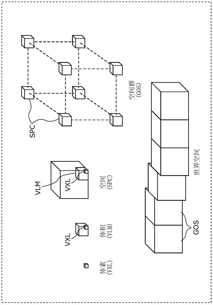
[0131] First, the data structure of encoded three-dimensional data (hereinafter also referred to as encoded data) according to the present embodiment will be described. figure 1 The structure of encoded three-dimensional data according to this embodiment is shown.
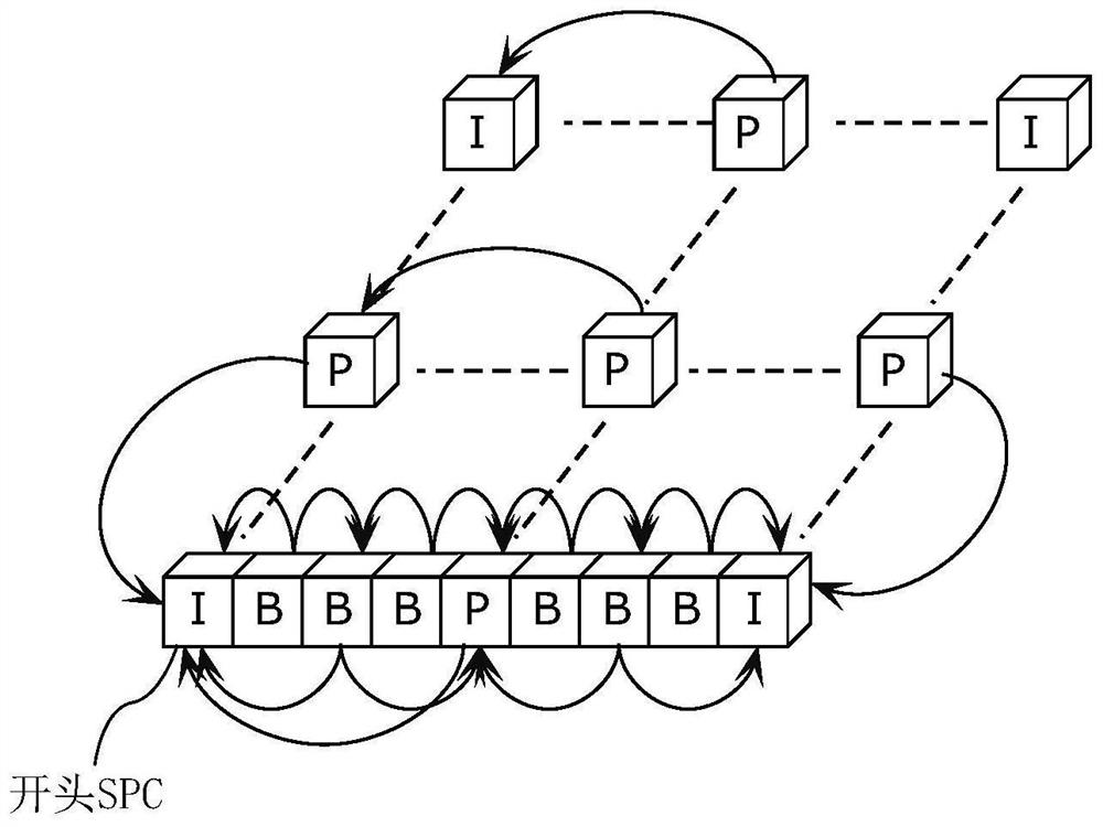
[0132] In the present embodiment, the three-dimensional space is divided into spaces (SPC) corresponding to pictures in encoding of moving images, and three-dimensional data is encoded in space units. The space is further divided into volumes (VLMs) equivalent to macroblocks in video coding, and prediction and conversion are performed in units of VLMs. The volume includes voxels (VXL), which are the smallest unit corresponding to position coordinates. In addition, prediction refers to generating predicted three-dimensional data similar to the processing unit of the processing target by referring to other processing units, and calculating the difference between the predicted three-dimensional data and the processing unit of the processing target, similar to the prediction performed on two-dimensional images. coding. Furthermore, this prediction includes not only spatial prediction referring to another prediction unit at the same time, but also temporal prediction referring to a prediction unit at a different time.
[0133] For example, when a three-dimensional data encoding device (hereinafter also referred to as an encoding device) encodes a three-dimensional space represented by point cloud data such as a point cloud, each point of the point cloud or all points within a voxel are encoded according to the size of the voxel. Included multiple points are coded together. By subdividing the voxels, it is possible to express the three-dimensional shape of the point cloud with high precision, and by increasing the size of the voxel, it is possible to roughly express the three-dimensional shape of the point cloud.
[0134] In addition, although the case where the 3D data is a point cloud is used as an example for description below, the 3D data is not limited to the point cloud, and may be 3D data in any form.
[0135] Also, hierarchically structured voxels can be utilized. In this case, in the n-order hierarchy, whether or not there are sampling points in the n-1 or lower hierarchy (the lower layer of the n-order hierarchy) can be sequentially displayed. For example, when decoding only the n-order hierarchy, if there are sampling points in the n-1 or less hierarchy, it can be decoded as if there is a sampling point in the center of the voxel in the n-order hierarchy.
[0136] In addition, the encoding device obtains point cloud data through a distance sensor, a stereo camera, a monocular camera, a gyroscope, or an inertial sensor.
[0137] Regarding space, similar to the encoding of moving images, it is classified into at least one of the following three prediction structures: Intra spatial (I-SPC) that can be decoded independently, and prediction that can only refer to one direction space (P-SPC), and bidirectional space (B-SPC) capable of bidirectional reference. In addition, the space has two kinds of time information, the decoding time and the display time.
[0138] and, if figure 1 As shown, as a processing unit including a plurality of spaces, there is a GOS (Group Of Space: Space Group) which is a random access unit. Also, as a processing unit including a plurality of GOSs, there is a world space (WLD).
[0139] The space area occupied by the world space corresponds to the absolute position on the earth through GPS or latitude and longitude information. This positional information is stored as meta information. In addition, meta information may be included in the coded data, or may be transmitted separately from the coded data.
[0140] In addition, in the GOS, all SPCs may be three-dimensionally adjacent, and there may be SPCs that are not three-dimensionally adjacent to other SPCs.
[0141] In addition, hereinafter, processing such as encoding, decoding, or referring to 3D data included in a processing unit such as GOS, SPC, or VLM is simply referred to as encoding, decoding, or referring to a processing unit. In addition, the three-dimensional data included in the processing unit includes at least one set of spatial positions such as three-dimensional coordinates and characteristic values ​​such as color information, for example.
[0142] Next, the prediction structure of the SPC in the GOS will be described. Although a plurality of SPCs in the same GOS or a plurality of VLMs in the same SPC occupy different spaces, they have the same time information (decoding time and display time).
[0143] Also, in the GOS, the first SPC in the decoding order is the I-SPC. In addition, there are two types of closed GOS and open GOS in GOS. A closed GOS is a GOS capable of decoding all SPCs in the GOS when decoding starts from the head I-SPC. In the open GOS, in the GOS, some SPCs earlier than the display time of the first I-SPC refer to a different GOS, and can only be decoded in that GOS.
[0144] In addition, in coded data such as map information, WLD may be decoded from the direction opposite to the coding order, and if there is a dependency between GOSs, it will be difficult to reproduce in the reverse direction. Therefore, in this case, a closed GOS is basically adopted.
[0145] In addition, the GOS has a layer structure in the height direction, and encoding or decoding is performed sequentially from the SPC of the lower layer.
[0146] figure 2 An example of the prediction structure between SPCs belonging to the lowest layer of the GOS is shown. image 3 An example of the prediction structure between layers is shown.
[0147] There is more than one I-SPC in the GOS. Objects such as people, animals, automobiles, bicycles, signal lights, and buildings serving as land marks exist in the three-dimensional space, but it is especially effective when encoding small objects as I-SPCs. For example, when a three-dimensional data decoding device (hereinafter also referred to as a decoding device) decodes a GOS at a low throughput or high speed, it decodes only the I-SPC in the GOS.
[0148] In addition, the encoding device may switch the encoding interval or frequency of appearance of the I-SPC according to the density of objects in the WLD.
[0149] and, in image 3 In the shown configuration, the encoding device or the decoding device sequentially encodes or decodes a plurality of layers starting from the lower layer (layer 1). Accordingly, for example, for an autonomous vehicle or the like, it is possible to increase the priority of data near the ground with a large amount of information.
[0150] In addition, in coded data used by a drone or the like, coding or decoding may be performed sequentially from the SPC of the upper layer in the height direction within the GOS.
[0151] Furthermore, the encoding device or the decoding device may encode or decode a plurality of layers in such a manner that the decoding device roughly grasps the GOS and can gradually increase the resolution. For example, an encoding device or a decoding device may perform encoding or decoding in the order of layers 3, 8, 1, 9, . . .
[0152] Next, methods corresponding to static objects and dynamic objects will be described.
[0153] In the three-dimensional space, there are static objects or scenes such as buildings or roads (hereinafter collectively referred to as static objects), and dynamic objects such as vehicles or people (hereinafter referred to as dynamic objects). Object detection can be performed separately by extracting feature points from point cloud data, or images captured by a stereo camera or the like. Here, an example of a method of encoding a dynamic object will be described.
[0154] The first method is a method of coding without distinguishing between static objects and dynamic objects. The second method is a method of distinguishing a static object and a dynamic object by identification information.
[0155] For example, GOS is used as a unit of identification. In this case, the GOS including the SPC constituting the static object is distinguished from the GOS including the SPC constituting the dynamic object in coded data or by identification information stored separately from the coded data.
[0156] Alternatively, SPCs are used as identification units. In this case, an SPC including only VLMs constituting static objects and an SPC including VLMs constituting dynamic objects are distinguished by the above-mentioned identification information.
[0157] Alternatively, VLM or VXL can be used as the recognition unit. In this case, the VLM or VXL including static objects is distinguished from the VLM or VXL including dynamic objects by the above-mentioned identification information.
[0158] Furthermore, the encoding device may encode the dynamic object as one or more VLMs or SPCs, and encode the VLM or SPC including the static object and the SPC including the dynamic object as mutually different GOSs. Furthermore, when the size of the GOS is variable according to the size of the dynamic object, the encoding device separately stores the size of the GOS as meta information.
[0159] Furthermore, the encoding device encodes the static objects and the dynamic objects independently of each other, so that the dynamic objects can be superimposed on the world space composed of the static objects. At this time, the dynamic object is composed of one or more SPCs, and each SPC corresponds to one or more SPCs constituting the static object on which the SPC is superimposed. In addition, dynamic objects may not be represented by SPC, but may be represented by one or more VLMs or VXLs.
[0160] Also, the encoding device may encode the static object and the dynamic object as streams that are different from each other.
[0161] Furthermore, the encoding device may generate a GOS including one or more SPCs constituting a dynamic object. Furthermore, the encoding device may set the GOS (GOS_M) including the dynamic object and the GOS of the static object corresponding to the spatial area of ​​the GOS_M to have the same size (occupy the same spatial area). In this way, superimposition processing can be performed in units of GOS.
[0162] The P-SPC or B-SPC constituting the dynamic object may also refer to the SPC included in the encoded different GOS. When the position of a dynamic object changes with time and the same dynamic object is coded as GOS at different times, reference across GOS is effective from the viewpoint of compression rate.
[0163]In addition, the first method and the second method described above may be switched according to the usage of the coded data. For example, when the encoded three-dimensional data is used as a map, since it is desired to separate it from the dynamic object, the encoding device adopts the second method. In addition, when the encoding device encodes three-dimensional data of an event such as a concert or sports, the first method is adopted if it is not necessary to separate dynamic objects.
[0164] In addition, the decoding time and display time of GOS or SPC can be stored in coded data or stored as meta information. Also, the time information of the static objects may all be the same. At this time, the actual decoding time and display time can be determined by the decoding device. Alternatively, different values ​​may be given for each GOS or SPC as the decoding time, and the same value may be given as the display time for all. Furthermore, as shown in the decoder mode in video coding such as HRD (Hypothetical Reference Decoder) of HEVC, the decoder has a buffer of a predetermined size, and the bit stream can be read at a predetermined bit rate according to the decoding time. Import a model that is not corrupted and is guaranteed to be decodable.
[0165] Next, the arrangement of the GOS in the world space will be described. The coordinates of the three-dimensional space in the world space are represented by three coordinate axes (x axis, y axis, z axis) orthogonal to each other. By setting a predetermined rule in the encoding order of GOS, spatially adjacent GOS can be continuously encoded in the encoded data. For example in Figure 4 In the example shown, the GOS in the xz plane is coded consecutively. After the encoding of all GOSs in an xz plane is completed, the value of the y-axis is updated. That is, as encoding continues, the world space extends toward the y-axis. And, the index number of GOS is set as the coding order.
[0166] Here, the three-dimensional space of the world space is in one-to-one correspondence with absolute geographic coordinates such as GPS or latitude and longitude. Alternatively, the three-dimensional space may be represented by a relative position with respect to a preset reference position. The directions of the x-axis, y-axis, and z-axis in the three-dimensional space are expressed as direction vectors determined based on latitude, longitude, etc., and the direction vectors are stored together with the coded data as meta information.
[0167] Also, the size of the GOS is set to be fixed, and the encoding device stores this size as meta information. In addition, the size of the GOS can be switched according to whether it is in the city, indoors, or outdoors, for example. That is, the size of the GOS can be switched according to the amount or nature of objects having value as information. Alternatively, the encoding device may appropriately switch the size of the GOS or the interval of the I-SPCs in the GOS according to the density of the objects in the same world space. For example, the encoding device sets the size of the GOS to be smaller and the interval of I-SPCs in the GOS to be shorter as the object density is higher.
[0168] exist Figure 5 In the example of , in the area from the 3rd to the 10th GOS, since the density of objects is high, the GOS is subdivided in order to realize the random access of fine granularity. And, the 7th to 10th GOS exist on the back side of the 3rd to 6th GOS, respectively.
[0169] Next, the configuration and operation flow of the three-dimensional data encoding device according to the present embodiment will be described. Image 6 is a block diagram of the three-dimensional data encoding device 100 according to this embodiment. Figure 7 It is a flowchart showing an example of the operation of the three-dimensional data encoding device 100 .
[0170] Image 6 The illustrated three-dimensional data encoding device 100 generates encoded three-dimensional data 112 by encoding three-dimensional data 111 . This three-dimensional data encoding device 100 includes an acquisition unit 101 , an encoding region determination unit 102 , a division unit 103 , and an encoding unit 104 .
[0171] like Figure 7 As shown, first, the obtaining unit 101 obtains the three-dimensional data 111 as point cloud data (S101).
[0172] Next, the encoding region determination unit 102 determines an encoding target region from the spatial regions corresponding to the obtained point cloud data ( S102 ). For example, according to the position of the user or the vehicle, the encoding area determination unit 102 determines a spatial area around the position as the area to be encoded.
[0173] Next, the division unit 103 divides the point cloud data included in the region to be encoded into each processing unit. Here, the processing unit is the above-mentioned GOS, SPC, and the like. Furthermore, the region to be coded corresponds to, for example, the above-mentioned world space. Specifically, the dividing unit 103 divides the point cloud data into processing units according to the size of the GOS set in advance and the presence or absence or size of dynamic objects ( S103 ). Then, the division unit 103 determines the start position of the leading SPC in the coding order in each GOS.
[0174] Next, the encoding unit 104 generates encoded three-dimensional data 112 by sequentially encoding a plurality of SPCs in each GOS (S104).
[0175] In addition, although an example is shown in which each GOS is encoded after dividing the encoding target area into GOS and SPC, the order of processing is not limited to the above. For example, after the configuration of one GOS is determined, the GOS may be coded, and then the order of the configuration of the GOS may be determined.
[0176] In this way, the three-dimensional data encoding device 100 encodes the three-dimensional data 111 to generate the encoded three-dimensional data 112 . Specifically, the three-dimensional data encoding device 100 divides the three-dimensional data into random access units, that is, into first processing units (GOS) respectively corresponding to three-dimensional coordinates, and divides the first processing unit (GOS) into a plurality of second The processing unit (SPC) divides the second processing unit (SPC) into a plurality of third processing units (VLM). Furthermore, the third processing unit (VLM) includes one or more voxels (VXL), and a voxel (VXL) is a minimum unit corresponding to position information.
[0177] Next, the three-dimensional data encoding device 100 generates encoded three-dimensional data 112 by encoding each of the plurality of first processing units (GOS). Specifically, the three-dimensional data encoding device 100 encodes each of a plurality of second processing units (SPCs) in each first processing unit (GOS). Furthermore, the three-dimensional data encoding device 100 encodes each of a plurality of third processing units (VLM) in each second processing unit (SPC).
[0178] For example, when the first processing unit (GOS) to be processed is a closed-type GOS, the three-dimensional data encoding device 100 executes the second processing unit (SPC) included in the first processing unit (GOS) to , coded with reference to another second processing unit (SPC) included in the first processing unit (GOS) of the processing target. That is, the three-dimensional data encoding device 100 does not refer to the second processing unit (SPC) included in the first processing unit (GOS) different from the processing target first processing unit (GOS).
[0179] And, when the first processing unit (GOS) of the processing target is an open GOS, for the second processing unit (SPC) of the processing target included in the first processing unit (GOS) of the processing target, refer to the Another second handling unit (SPC) included in the first handling unit (GOS), or a second handling unit (SPC) included in a first handling unit (GOS) different from the first handling unit (GOS) ) to encode.
[0180] In addition, the three-dimensional data encoding device 100 never refers to the first type (I-SPC) of another second processing unit (SPC) as the type of the second processing unit (SPC) to be processed, and refers to another second processing unit (SPC). Select one of the second type (P-SPC) of the processing unit (SPC) and the third type referring to the other two second processing units (SPC), and the second processing unit of the processing object according to the selected type (SPC) for encoding.
[0181] Next, the configuration and operation flow of the three-dimensional data decoding device according to the present embodiment will be described. Figure 8 is a block diagram of the three-dimensional data decoding device 200 according to this embodiment. Figure 9 It is a flowchart showing an example of the operation of the three-dimensional data decoding device 200 .
[0182] Figure 8 The illustrated three-dimensional data decoding device 200 generates decoded three-dimensional data 212 by decoding encoded three-dimensional data 211 . Here, the encoded three-dimensional data 211 is, for example, the encoded three-dimensional data 112 generated by the three-dimensional data encoding device 100 . The three-dimensional data decoding device 200 includes an acquisition unit 201 , a decoding start GOS determination unit 202 , a decoding SPC determination unit 203 , and a decoding unit 204 .
[0183] First, the obtaining unit 201 obtains encoded three-dimensional data 211 (S201). Next, the decoding start GOS determination unit 202 determines a GOS to be decoded (S202). Specifically, the decoding start GOS determination unit 202 refers to the meta information stored in the encoded three-dimensional data 211 or separately from the encoded three-dimensional data, and determines the GOS including the spatial position at which decoding starts, the object, or the SPC corresponding to the time as the decoding target. GOS.
[0184] Next, the decoding SPC determination unit 203 determines the type (I, P, B) of the SPC to be decoded in the GOS (S203). For example, the decoding SPC determination unit 203 determines (1) whether to decode only I-SPC, (2) whether to decode I-SPC and P-SPC, and (3) whether to decode all types. In addition, when the type of SPC to be decoded is predetermined, such as decoding all SPCs, this step does not need to be performed.
[0185] Next, the decoding unit 204 obtains the first SPC in the decoding order (same as the encoding order) in the GOS, the address position starting in the encoded three-dimensional data 211, obtains the encoded data of the first SPC from the address position, and obtains the encoded data of the first SPC from the address position. Each SPC is decoded in sequence (S204). And, the above-mentioned address position is stored in meta information or the like.
[0186] In this way, the three-dimensional data decoding device 200 decodes the decoded three-dimensional data 212 . Specifically, the three-dimensional data decoding device 200 generates a first processing unit (GOS) as a random access unit by decoding each of the encoded three-dimensional data 211 of the first processing unit (GOS) corresponding to the three-dimensional coordinates. The decoded three-dimensional data 212. More specifically, the three-dimensional data decoding device 200 decodes each of the plurality of second processing units (SPC) in each first processing unit (GOS). Furthermore, the three-dimensional data decoding device 200 decodes each of the plurality of third processing units (VLM) in each second processing unit (SPC).
[0187] Meta information for random access will be described below. This meta information is generated by the three-dimensional data encoding device 100 and included in the encoded three-dimensional data 112 (211).
[0188] In the conventional random access of two-dimensional moving pictures, decoding starts from the head frame of the random access unit near the specified time. However, in world space, random access to (coordinates or objects, etc.) is conceived in addition to time.
[0189] Therefore, in order to realize random access to at least three elements of coordinates, objects, and time, a table is prepared in which each element is associated with an index number of the GOS. Furthermore, the index number of the GOS is associated with the address of the I-SPC that becomes the head of the GOS. Figure 10 An example of a table included in meta information is shown. Also, there is no need to use Figure 10Of all the tables shown, at least one table is sufficient.
[0190] Random access starting from coordinates will be described below as an example. When accessing the coordinates (x2, y2, z2), first referring to the coordinate-GOS table, it can be known that the point with the coordinates (x2, y2, z2) is included in the second GOS. Next, referring to the GOS address table, since it is known that the address of the first I-SPC in the second GOS is addr(2), the decoding unit 204 obtains data from this address and starts decoding.
[0191] In addition, the address may be an address in a logical format, or a physical address of an HDD or a memory. In addition, instead of the address, information specifying the file segment may be used. For example, a file segment is a unit obtained by segmenting one or more GOS and the like.
[0192] Furthermore, when the object spans a plurality of GOSs, the GOS to which the plurality of objects belong may be shown in the object GOS table. If the plurality of GOSs are closed GOSs, the encoding device and the decoding device can perform encoding or decoding in parallel. In addition, if the plurality of GOSs are open GOSs, the plurality of GOSs can refer to each other, thereby further improving compression efficiency.
[0193] Examples of objects include people, animals, automobiles, bicycles, signal lights, and buildings serving as landmarks on land. For example, when encoding the three-dimensional data in the world space, the three-dimensional data encoding device 100 extracts characteristic points specific to an object from a three-dimensional point cloud or the like, detects an object based on the characteristic points, and can set the detected object as a random access point. .
[0194] In this manner, the three-dimensional data encoding device 100 generates first information indicating a plurality of first processing units (GOS) and three-dimensional coordinates corresponding to each of the plurality of first processing units (GOS). And, the coded three-dimensional data 112 (211) includes the first information. In addition, the first information further indicates at least one of the object, time, and data storage destination corresponding to each of the plurality of first processing units (GOS).
[0195] The three-dimensional data decoding device 200 obtains the first information from the encoded three-dimensional data 211, uses the first information to determine the encoded three-dimensional data 211 of the first processing unit corresponding to the specified three-dimensional coordinates, object or time, and 211 for decoding.
[0196] Examples of other meta information will be described below. In addition to the random access meta information, the three-dimensional data encoding device 100 can generate and store the following meta information. Furthermore, the three-dimensional data decoding device 200 may also use the meta information when decoding.
[0197] In the case of using three-dimensional data as map information, etc., a profile is defined according to the usage, and information indicating the profile may be included in the meta information. For example, the level facing urban areas or suburbs, or the level facing flying objects is specified, and the world space, the maximum or minimum size of SPC or VLM are respectively defined. For example, in an urban-oriented profile, more detailed information is required than in the suburbs, so the minimum size of the VLM is set smaller.
[0198] Meta information may also include a tag value showing the category of the object. This tag value corresponds to the VLM, SPC, or GOS constituting the object. Tag values ​​can be set according to the type of object, for example, tag value "0" means "person", tag value "1" means "vehicle", tag value "2" means "signal light". Alternatively, when it is difficult to judge the type of object or does not need to be judged, a tag value representing properties such as size, dynamic object or static object can also be used.
[0199] Also, the meta information may include information showing the range of the space area occupied by the world space.
[0200] Furthermore, the meta information may store the size of the SPC or VXL as header information shared by the entire stream of encoded data or a plurality of SPCs such as the SPC in the GOS.
[0201] In addition, the meta information may include identification information such as a distance sensor or a camera used to generate the point cloud, or information indicating the positional accuracy of point groups in the point cloud.
[0202] And, the meta information may include information showing whether the world space is composed of only static objects or contains dynamic objects.
[0203] Modifications of the present embodiment will be described below.
[0204] The encoding device or the decoding device can encode or decode two or more different SPCs or GOSs in parallel. The GOS to be coded or decoded in parallel can be determined from meta information indicating the spatial position of the GOS or the like.
[0205] In the case of using three-dimensional data as a spatial map when a vehicle or flying object moves, or generating such a spatial map, the encoding device or decoding device may use the data determined based on GPS, route information, or magnification, etc. GOS or SPC contained in the space for encoding or decoding.
[0206] In addition, the decoding device may perform decoding sequentially from the space closest to the own position or the travel route. The encoding device or the decoding device may perform encoding or decoding by lowering the priority of a space farther from its own position or travel path than a space closer to it. Here, lowering the priority refers to lowering the processing order, lowering the resolution (post-filtering processing), or lowering the image quality (enhancing coding efficiency. For example, increasing the quantization step size), and the like.
[0207] Furthermore, when the decoding device decodes coded data that has been hierarchically coded in space, it may decode only lower layers.
[0208] In addition, the decoding device may decode from the lower layer first according to the scaling factor or application of the map.
[0209] In addition, in applications such as self-position estimation or object recognition performed during autonomous driving of automobiles or robots, the encoding device or decoding device can also distinguish the area other than the area within a predetermined height from the road surface (the identification area) Rate reduction for encoding or decoding.
[0210] In addition, the encoding device may independently encode point clouds expressing indoor and outdoor spatial shapes. For example, by separating the GOS representing indoor (indoor GOS) from the GOS representing outdoor (outdoor GOS), the decoding device can select a GOS to be decoded according to the viewpoint position when using coded data.
[0211] Furthermore, the encoding device may encode the indoor GOS and the outdoor GOS adjacent to each other in the encoded stream. For example, the encoding device associates the two identifiers, and stores information indicating the associated identifier in the encoded stream or in separately stored meta information. Accordingly, the decoding device can identify the indoor GOS and the outdoor GOS with close coordinates by referring to the information in the meta information.
[0212] Furthermore, the encoding device may switch the size of the GOS or the SPC between the indoor GOS and the outdoor GOS. For example, the encoding device sets the size of the GOS smaller indoors than outdoors. Furthermore, the encoding device may change the accuracy of extracting feature points from point clouds, the accuracy of object detection, and the like between the indoor GOS and the outdoor GOS.
[0213] Also, the encoding device may add information for the decoding device to distinguish and display the dynamic object from the static object to the encoded data. Accordingly, the decoding device can display a dynamic object in combination with a red frame, explanatory characters, and the like. In addition, instead of the dynamic object, the decoding device may be represented by only a red frame or explanatory characters. And, the decoding device can represent more detailed object categories. For example, a car may have a red frame and a person may have a yellow frame.
[0214] Furthermore, the encoding device or the decoding device may determine whether to perform encoding or decoding by considering the dynamic object and the static object as different SPCs or GOSs according to the frequency of appearance of the dynamic object or the ratio of the static object to the dynamic object. For example, when the frequency or ratio of dynamic objects exceeds the threshold, SPC or GOS where dynamic objects and static objects are mixed is allowed; when the frequency or ratio of dynamic objects does not exceed the threshold, dynamic objects and static objects SPC or GOS where static objects are mixed will not be allowed.
[0215] When the dynamic object is detected not from the point cloud but from the two-dimensional image information of the camera, the encoding device can separately obtain the information (frame or text, etc.) used to identify the detection result and the object position, and use these information as three-dimensional encoded data part of the code. In this case, the decoding device superimposes and displays auxiliary information (frames or characters) indicating the dynamic object on the decoding result of the static object.
[0216] In addition, the encoding device may change the density of the VXL or VLM according to the complexity of the shape of the static object or the like. For example, the encoding device sets VXL or VLM to be denser when the shape of the static object is more complicated. Furthermore, the encoding device may determine the quantization step size when quantizing the spatial position or color information according to the degree of density of VXL or VLM. For example, the encoding device sets the quantization width smaller as the VXL or VLM becomes denser.
[0217] As described above, the encoding device or decoding device according to the present embodiment performs spatial encoding or decoding in units of spaces having coordinate information.
[0218] In addition, the encoding device and the decoding device perform encoding or decoding in units of volumes in space. The volume includes a voxel which is the smallest unit corresponding to position information.
[0219] Furthermore, the encoding device and the decoding device associate arbitrary elements with a table that associates each element of spatial information including coordinates, objects, and time with a GOP, or a table that associates each element with each other. Encode or decode. Furthermore, the decoding device judges the coordinates using the value of the selected element, specifies a volume, voxel, or space based on the coordinates, and decodes the space including the volume or voxel, or the specified space.
[0220] Furthermore, the encoding device determines a volume, voxel, or space that can be selected from elements through feature point extraction or object recognition, and encodes it as a volume, voxel, or space that can be randomly accessed.
[0221] The space is divided into three types, namely: I-SPC that can be encoded or decoded by a single space, P-SPC that can be encoded or decoded with reference to any one processed space, and reference to any two processed spaces to encode or decode the B-SPC.
[0222] More than one volume corresponds to static objects or dynamic objects. The space containing static objects and the space containing dynamic objects are encoded or decoded as different GOS from each other. That is, SPCs containing static objects and SPCs containing dynamic objects are assigned to different GOSs.
[0223] Dynamic objects are encoded or decoded on a per-object basis, corresponding to one or more spaces containing only static objects. That is, a plurality of dynamic objects are encoded separately, and the obtained encoded data of the plurality of dynamic objects corresponds to an SPC including only static objects.
[0224] The encoding device and the decoding device increase the priority of the I-SPC in the GOS to perform encoding or decoding. For example, the encoding device performs encoding so that the degradation of I-SPC is reduced (after decoding, the original 3D data can be reproduced more faithfully). Also, the decoding device decodes only I-SPC, for example.
[0225]The encoding device may perform encoding by changing the frequency of using I-SPC according to the density or value (number) of objects in the world space. That is, the encoding device changes the frequency of selecting the I-SPC according to the number or density of objects included in the three-dimensional data. For example, the encoding device increases the frequency of use of the I space as the density of objects in the world space increases.
[0226] Then, the encoding device sets a random access point in units of GOS, and stores information indicating a spatial area corresponding to the GOS in the header information.
[0227] The encoding device adopts, for example, a default value as the space size of the GOS. In addition, the encoding device may change the size of the GOS according to the numerical value (number) or density of objects or dynamic objects. For example, the encoding device sets the space size of the GOS to be smaller when the objects or dynamic objects are denser or more in number.
[0228] Also, the space or volume includes a feature point group derived using information obtained by a sensor such as a depth sensor, a gyroscope, or a camera. The coordinates of the feature points are set as the center positions of the voxels. In addition, by subdividing voxels, it is possible to achieve high accuracy of position information.
[0229] A feature point group is derived using a plurality of images. A plurality of pictures has at least two kinds of time information, namely, actual time information and the same time information (for example, encoding time used for rate control, etc.) in the plurality of pictures corresponding to the space.
[0230] Furthermore, encoding or decoding is performed in units of GOS including one or more spaces.
[0231] The encoding device and the decoding device predict the P space or B space in the GOS to be processed by referring to the processed space in the GOS.
[0232] Alternatively, the encoding device and the decoding device predict the P space or the B space in the processing target GOS using the processed space in the processing target GOS without referring to different GOSs.
[0233] Furthermore, the encoding device and the decoding device transmit or receive encoded streams in units of world spaces including one or more GOSs.
[0234] In addition, the GOS has a layer structure in at least one direction in the world space, and the encoding device and the decoding device perform encoding or decoding from lower layers. For example, a GOS capable of random access belongs to the lowest layer. The GOS belonging to the upper layer only refers to the GOS belonging to the layer below the same layer. That is, the GOS is spatially divided in a predetermined direction and includes a plurality of layers each having one or more SPCs. The encoding device and the decoding device encode or decode each SPC by referring to an SPC included in the same layer as the SPC or a layer lower than the SPC.
[0235] In addition, the encoding device and the decoding device continuously encode or decode the GOS in a world space unit including a plurality of GOS. The encoding device and the decoding device write or read information indicating the sequence (direction) of encoding or decoding as metadata. That is, the encoded data includes information showing the encoding order of a plurality of GOSs.
[0236] Furthermore, the encoding device and the decoding device encode or decode two or more different spaces or GOSs in parallel.
[0237] Furthermore, the encoding device and the decoding device encode or decode the space or the space information (coordinates, size, etc.) of the GOS.
[0238] Furthermore, the encoding device and the decoding device encode or decode the space included in the specific space or the GOS specified based on external information such as GPS, route information, or magnification related to the self's position and/or area size.
[0239] An encoding device or a decoding device performs encoding or decoding by giving a lower priority to spaces far away from itself than to spaces close to itself.
[0240] The encoding device sets one direction in the world space according to the magnification or usage, and encodes the GOS having a layered structure in the direction. Furthermore, the decoding device preferentially decodes a GOS having a layered structure in one direction in the world space, which is set according to the magnification or usage, from the lower layer.
[0241] The encoding device changes the extraction of feature points contained in indoor and outdoor spaces, the accuracy of object recognition, or the size of a spatial region, and the like. However, the encoding device and the decoding device encode or decode the indoor GOS and the outdoor GOS with close coordinates adjacent to each other in the world space, and encode or decode these identifiers in association.

Example Embodiment

[0242] (Embodiment 2)
[0243] When point cloud coded data is used in an actual device or service, it is desirable to transmit and receive required information according to usage in order to suppress network bandwidth. However, such a function does not exist in the encoding structure of the three-dimensional data so far, and therefore there is no encoding method corresponding to it.
[0244] In this embodiment, a three-dimensional data coding method and a three-dimensional data coding device for providing a function of transmitting and receiving required information in accordance with usage in three-dimensional point cloud coded data, as well as the A three-dimensional data decoding method and a three-dimensional data decoding device for decoding coded data.
[0245] A voxel (VXL) having a certain feature value or more is defined as a feature voxel (FVXL), and a world space (WLD) configured with FVXL is defined as a sparse world space (SWLD). Figure 11 A sparse world space and a configuration example of the world space are shown. The SWLD includes: FGOS, a GOS composed of FVXL; FSPC, an SPC composed of FVXL; and FVLM, a VLM composed of FVXL. The data structures and prediction structures of FGOS, FSPC, and FVLM may be the same as those of GOS, SPC, and VLM.
[0246] The feature quantity refers to the feature quantity representing the three-dimensional position information of the VXL or the visible light information of the VXL position, and in particular, many feature quantities can be detected such as corners and edges of a three-dimensional object. Specifically, the feature amount is a three-dimensional feature amount or a feature amount of visible light described below, but any feature amount may be used as long as it is a feature amount indicating the position, brightness, or color information of the VXL. .
[0247] As the three-dimensional feature quantity, a SHOT feature quantity (Signature of Histograms of Orientations: orientation histogram feature), a PFH feature quantity (Point Feature Histograms: Point Feature Histogram), or a PPF feature quantity (Point Pair Feature: Point Pair Feature) is used.
[0248] The SHOT feature is obtained by segmenting the VXL periphery, calculating the inner product of the reference point and the normal vector of the segmented area, and performing histogramization. This SHOT feature quantity has the characteristics of high dimensionality and high feature expressiveness.
[0249] The PFH feature quantity is obtained by selecting a plurality of two-point groups near VXL, calculating a normal vector, etc. from these two points, and forming a histogram. Since the PFH feature quantity is a histogram feature, it is robust against a small amount of disturbance and has high feature expressiveness.
[0250] The PPF feature quantity is a feature quantity calculated using a normal vector or the like according to the two-point VXL. In this PPF feature quantity, since all VXLs are used, it has robustness against shading.
[0251] In addition, as the feature quantity of visible light, SIFT (Scale-Invariant Feature Transform: Scale-Invariant Feature Transform), SURF (Speeded Up Robust Features), or HOG (Histogram of Oriented Gradients: direction gradient histogram), etc.
[0252] The SWLD is generated by calculating the above-mentioned feature quantity from each VXL of the WLD, and extracting the FVXL. Here, the SWLD may be updated every time the WLD is updated, or it may be updated periodically after a certain period of time has elapsed regardless of the update timing of the WLD.
[0253] SWLD can be generated for each feature quantity. For example, as shown in SWLD1 based on SHOT feature quantities and SWLD2 based on SIFT feature quantities, it is possible to generate SWLDs for each feature quantity, and use SWLDs according to purposes. In addition, the calculated feature amount of each FVXL may be held in each FVXL as feature amount information.
[0254] Next, a method of using the sparse world space (SWLD) will be described. Since SWLD contains only feature voxels (FVXL), the data size is generally smaller compared to WLD including all VXL.
[0255] In an application in which a feature is used for a certain purpose, by using the information of the SWLD instead of the WLD, it is possible to reduce the read time from the hard disk, and to reduce the frequency band and transmission time during network transmission. For example, WLD and SWLD are stored in the server in advance as map information, and the network bandwidth and transmission time can be suppressed by switching the map information to be sent to WLD or SWLD according to the request from the client. Specific examples are shown below.
[0256] Figure 12 as well as Figure 13 An example of using SWLD and WLD is shown. like Figure 12 As shown, when the client 1, which is an in-vehicle device, needs map information for determining its own position, the client 1 sends a request to acquire map data for estimating its own position to the server (S301). The server sends the SWLD to the client 1 according to the acquisition requirement (S302). Client 1 uses the received SWLD to judge its own location (S303). At this time, the client 1 acquires the VXL information around the client 1 through various methods such as a distance sensor such as a rangefinder, a stereo camera, or a combination of multiple monocular cameras, and estimates itself based on the obtained VXL information and SWLD location information. Here, the own location information includes the three-dimensional location information and orientation of the client 1 .
[0257] like Figure 13 As shown, when the client 2 as an in-vehicle device needs map information for map drawing such as a three-dimensional map, the client 2 sends a request for acquiring map data for map drawing to the server (S311). The server sends the WLD to the client 2 according to the acquisition requirement (S312). The client 2 draws a map using the received WLD (S313). At this time, the client 2 creates a conceptual image using, for example, an image taken by itself with a visible light camera and a WLD acquired from a server, and draws the created image on a screen such as a car navigation.
[0258] As described above, the server transmits the SWLD to the client when the feature value of each VXL such as the estimation of its own position is mainly required, and transmits the WLD to the client when detailed VXL information is required, such as map drawing end. Accordingly, map data can be efficiently transmitted and received.
[0259] In addition, the client can determine which of the SWLD and WLD it needs, and request the server to send the SWLD or the WLD. In addition, the server can determine which one should be sent, SWLD or WLD, according to the status of the client or the network.
[0260]Next, a method of switching between the sparse world space (SWLD) and the world space (WLD) will be described.
[0261] The reception of WLD or SWLD can be switched according to the network bandwidth. Figure 14 A working example in this case is shown. For example, when a low-speed network capable of using network bandwidth such as in an LTE (Long Term Evolution: Long Term Evolution) environment is used, when the client accesses the server via the low-speed network (S321), the map is acquired from the server. SWLD of information (S322). In addition, when using a high-speed network with sufficient network bandwidth such as a WiFi environment, the client accesses the server via the high-speed network (S323), and acquires the WLD from the server (S324). Accordingly, the client can obtain appropriate map information according to the network bandwidth of the client.
[0262] Specifically, the client receives SWLD via LTE outdoors, and acquires WLD via WiFi when entering a room such as a facility. Accordingly, the client can acquire more detailed indoor map information.
[0263] In this way, the client can request WLD or SWLD from the server according to the frequency band of the network it uses. Alternatively, the client may transmit information indicating the frequency band of the network used by itself to the server, and the server may transmit appropriate data (WLD or SWLD) to the client according to the information. Alternatively, the server can determine the network bandwidth of the client and send appropriate data (WLD or SWLD) to the client.
[0264] Also, the reception of WLD or SWLD can be switched according to the moving speed. Figure 15 A working example in this case is shown. For example, when the client moves at high speed (S331), the client receives the SWLD from the server (S332). Also, when the client moves at a low speed (S333), the client receives the WLD from the server (S334). Accordingly, the client can not only suppress the network bandwidth, but also obtain the map information according to the speed. Specifically, the client can update the map information at an approximately appropriate speed by receiving the SWLD with a small amount of data while driving on the highway. In addition, when the client is driving on a general road, by receiving the WLD, more detailed map information can be acquired.
[0265] In this way, the client can request WLD or SWLD from the server according to its own moving speed. Alternatively, the client may transmit information indicating its own moving speed to the server, and the server may transmit appropriate data (WLD or SWLD) to the client according to the information. Alternatively, the server can determine the moving speed of the client and send the appropriate data (WLD or SWLD) to the client.
[0266] Moreover, it may also be that the client first obtains the SWLD from the server, and then obtains the WLD of important areas therein. For example, when the client acquires map data, it first acquires rough map information with SWLD, from which it screens out areas where many features such as buildings, signs, or people appear, and then obtains the WLD of the filtered area. Accordingly, the client can acquire detailed information on the desired area while suppressing the amount of received data from the server.
[0267] In addition, the server may create SWLD for each object based on WLD, and the client may receive it for each purpose. According to this, the network bandwidth can be suppressed. For example, the server pre-identifies a person or a vehicle from the WLD, and creates a person's SWLD and a vehicle's SWLD. The client receives the SWLD of the person when it wants to acquire the information of the people around it, and receives the SWLD of the car when it wants to acquire the information of the car. Also, the type of this SWLD can be distinguished by information (flag, type, etc.) added to the header.
[0268] Next, the configuration and operation flow of the three-dimensional data encoding device (for example, server) according to the present embodiment will be described. Figure 16 is a block diagram of the three-dimensional data encoding device 400 according to this embodiment. Figure 17 This is a flowchart of the three-dimensional data encoding process performed by the three-dimensional data encoding device 400 .
[0269] Figure 16 The illustrated three-dimensional data encoding device 400 encodes input three-dimensional data 411 to generate encoded three-dimensional data 413 and 414 as encoded streams. Here, encoded 3D data 413 is encoded 3D data corresponding to WLD, and encoded 3D data 414 is encoded 3D data corresponding to SWLD. This three-dimensional data encoding device 400 includes an acquisition unit 401 , an encoding region determination unit 402 , an SWLD extraction unit 403 , a WLD encoding unit 404 , and a SWLD encoding unit 405 .
[0270] like Figure 17 As shown, first, the obtaining unit 401 obtains input three-dimensional data 411 that is point cloud data in a three-dimensional space (S401).
[0271] Next, the encoding area determination unit 402 determines an encoding target spatial area based on the spatial area where the point cloud data exists (S402).
[0272] Next, the SWLD extraction unit 403 defines a spatial region to be encoded as a WLD, and calculates a feature value from each VXL included in the WLD. Then, the SWLD extraction unit 403 extracts VXL whose feature value is equal to or greater than a predetermined threshold, defines the extracted VXL as FVXL, and adds the FVXL to the SWLD to generate extracted three-dimensional data 412 (S403). That is, extracted three-dimensional data 412 whose feature value is equal to or greater than a threshold value is extracted from input three-dimensional data 411 .
[0273] Next, the WLD encoding unit 404 encodes the input 3D data 411 corresponding to the WLD, thereby generating encoded 3D data 413 corresponding to the WLD ( S404 ). At this time, the WLD encoding unit 404 adds information for distinguishing the encoded 3D data 413 as a stream including WLD to the header of the encoded 3D data 413 .
[0274] Then, the SWLD encoding unit 405 encodes the extracted three-dimensional data 412 corresponding to SWLD, thereby generating encoded three-dimensional data 414 corresponding to SWLD ( S405 ). At this time, the SWLD encoding unit 405 adds information for distinguishing that the encoded 3D data 414 is a stream including SWLD to the header of the encoded 3D data 414 .
[0275] In addition, the processing order of the process of generating the coded three-dimensional data 413 and the process of generating the coded three-dimensional data 414 may be reversed from the above. Furthermore, part or all of the above-described processing may be executed in parallel.
[0276] As information given to the headers of the coded three-dimensional data 413 and 414 , for example, a parameter called "world_type" is defined. When world_type=0, it indicates that the stream includes WLD, and when world_type=1, it indicates that the stream includes SWLD. In the case of defining other more categories, it is possible to increase the allocated numerical value such as world_type=2. Also, a specific flag may be included in one of the encoded three-dimensional data 413 and 414 . For example, the encoded 3D data 414 may be given a flag indicating that the stream contains SWLD. In this case, the decoding device can determine whether the stream includes WLD or the stream includes SWLD based on the presence or absence of the flag.
[0277] Also, the encoding method used when the WLD encoding unit 404 encodes the WLD may be different from the encoding method used when the SWLD encoding unit 405 encodes the SWLD.
[0278] For example, since SWLD data is decimated, the correlation with peripheral data may be lower than that of WLD. Therefore, in the encoding method for SWLD, inter prediction among intra prediction and inter prediction is given priority over the encoding method for WLD.
[0279] In addition, the encoding method used for SWLD and the encoding method used for WLD may have different representation methods for three-dimensional positions. For example, the three-dimensional position of FVXL may be represented by three-dimensional coordinates in FWLD, and the three-dimensional position in WLD may be represented by an octree described later, and vice versa.
[0280] Furthermore, the SWLD encoding unit 405 performs encoding so that the data size of the encoded 3D data 414 of the SWLD is smaller than the data size of the encoded 3D data 413 of the WLD. For example, as described above, the correlation between data may be lower in SWLD than in WLD. As a result, the encoding efficiency decreases, and the data size of the encoded three-dimensional data 414 may be larger than the data size of the encoded three-dimensional data 413 of WLD. Therefore, when the data size of the obtained coded 3D data 414 is larger than the data size of the WLD coded 3D data 413 , the SWLD coder 405 re-codes to regenerate the coded 3D data 414 with a reduced data size.
[0281] For example, the SWLD extraction unit 403 regenerates the extracted three-dimensional data 412 with a reduced number of extracted feature points, and the SWLD encoding unit 405 encodes the extracted three-dimensional data 412 . Alternatively, the degree of quantization in the SWLD encoding unit 405 may be coarsened. For example, in an octree structure described later, the degree of quantization can be made rough by rounding the data at the lowest layer.
[0282] In addition, the SWLD coding unit 405 does not need to generate the SWLD coded 3D data 414 when the data size of the SWLD coded 3D data 414 cannot be smaller than the data size of the WLD coded 3D data 413 . Alternatively, the encoded three-dimensional data 413 of the WLD may be copied to the encoded three-dimensional data 414 of the SWLD. That is, as the encoded three-dimensional data 414 of SWLD, the encoded three-dimensional data 413 of WLD can be used as it is.
[0283] Next, the configuration and operation flow of a three-dimensional data decoding device (for example, a client) according to this embodiment will be described. Figure 18 is a block diagram of the three-dimensional data decoding device 500 according to this embodiment. Figure 19 is a flowchart of the three-dimensional data decoding process performed by the three-dimensional data decoding device 500 .
[0284] Figure 18 The illustrated three-dimensional data decoding apparatus 500 generates decoded three-dimensional data 512 or 513 by decoding encoded three-dimensional data 511 . Here, the encoded three-dimensional data 511 is, for example, the encoded three-dimensional data 413 or 414 generated by the three-dimensional data encoding device 400 .
[0285] This three-dimensional data decoding device 500 includes an acquisition unit 501 , a header analysis unit 502 , a WLD decoding unit 503 , and an SWLD decoding unit 504 .
[0286] like Figure 19 As shown, first, the obtaining unit 501 obtains encoded three-dimensional data 511 (S501). Next, the header analysis unit 502 analyzes the header of the encoded three-dimensional data 511, and determines whether the encoded three-dimensional data 511 is a stream including WLD or a stream including SWLD (S502). For example, the above-mentioned parameter of world_type is referred to for determination.
[0287] When the encoded 3D data 511 is a stream including WLD (YES in S503 ), the WLD decoding unit 503 decodes the encoded 3D data 511 to generate WLD decoded 3D data 512 ( S504 ). Also, when the encoded 3D data 511 is a stream including SWLD (No in S503 ), the SWLD decoding unit 504 decodes the encoded 3D data 511 to generate decoded 3D data 513 of SWLD ( S505 ).
[0288]Also, similarly to the encoding device, the decoding method used when the WLD decoding unit 503 decodes WLD may be different from the decoding method used when the SWLD decoding unit 504 decodes SWLD. For example, in the decoding method for SWLD, the intra prediction and the inter prediction among the inter prediction may be prioritized over the decoding method for WLD.
[0289] Furthermore, the method of expressing the three-dimensional position may be different between the decoding method for SWLD and the decoding method for WLD. For example, the three-dimensional position of FVXL can be represented by three-dimensional coordinates in SWLD, and the three-dimensional position can be represented by an octree described later in WLD, and vice versa.
[0290] Next, octree representation, which is a representation method of a three-dimensional position, will be described. The VXL data included in the 3D data is converted into an octree structure and encoded. Figure 20 An example of VXL for WLD is shown. Figure 21 show Figure 20 The octree structure of WLD is shown. exist Figure 20 In the example shown, there are three VXLs 1 to 3 that are VXLs (hereinafter, effective VXLs) including point groups. like Figure 21 As shown, the octree structure is composed of nodes and leaf nodes. Each node has a maximum of 8 nodes or leaf nodes. Each leaf node has VXL information. here, Figure 21 Among the leaf nodes shown, leaf nodes 1, 2, and 3 respectively represent Figure 20 VXL1, VXL2, VXL3 shown.
[0291] Specifically, each node and leaf node corresponds to a three-dimensional position. node 1 with Figure 20 All blocks shown correspond to . The block corresponding to node 1 is divided into 8 blocks, and among the 8 blocks, a block including valid VXL is set as a node, and the other blocks are set as leaf nodes. A block corresponding to a node is further divided into 8 nodes or leaf nodes, and this process is repeated as many times as the number of levels in the tree structure. And, all the blocks of the lowest layer are set as leaf nodes.
[0292] and, Figure 22 shows from Figure 20 An example of SWLD generated by WLD is shown. Figure 20 The results of the feature quantity extraction of the shown VXL1 and VXL2 are judged as FVXL1 and FVXL2 and added to the SWLD. In addition, VXL3 is not judged as FVXL, so it is not included in SWLD. Figure 23 show Figure 22 The octree structure of SWLD is shown. exist Figure 23 In the octree structure shown, Figure 21 The leaf node 3 shown corresponding to VXL3 is deleted. Accordingly, Figure 21 Node 3 is shown without a valid VXL and has been changed to a leaf node. In this way, generally speaking, the number of leaf nodes of SWLD is smaller than that of WLD, and the coded three-dimensional data of SWLD is also smaller than that of WLD.
[0293] Modifications of the present embodiment will be described below.
[0294] For example, when a client such as a vehicle-mounted device estimates its own position, it receives the SWLD from the server, uses the SWLD to estimate its own position, and detects obstacles, using distance sensors such as rangefinders, stereo cameras, Various methods, such as a combination of single-lens cameras or multiple cameras, perform obstacle detection based on the three-dimensional information of the surrounding area obtained by itself.
[0295] And, in general, it is difficult to include VXL data for flat regions in SWLD. For this purpose, the server holds a downsampled world space (SubWLD) in which the WLD is downsampled for detection of stationary obstacles, and may transmit the SWLD and the SubWLD to the client. Accordingly, the network bandwidth can be suppressed, and self-position estimation and obstacle detection can be performed on the client side.
[0296] Moreover, when the client quickly draws three-dimensional map data, it is convenient for the map information to have a grid structure. Then, the server can generate a mesh according to the WLD, and hold it in advance as a mesh world space (MWLD). For example, when the client needs to perform rough 3D rendering, it receives MWLD, and when it needs to perform detailed 3D rendering, it receives WLD. According to this, the network bandwidth can be suppressed.
[0297] Furthermore, although the server sets the VXL whose feature amount is equal to or greater than the threshold value as FVXL among the VXLs, it may calculate the FVXL by a different method. For example, if the server judges that VXL, VLM, SPC, or GOS constituting signals or intersections are necessary for self-position estimation, driving assistance, or automatic driving, etc., they can be included in SWLD as FVXL, FVLM, FSPC, and FGOS. . In addition, the above determination can be performed manually. In addition, FVXL and the like obtained by the above method may be added to the FVXL and the like set based on the feature amount. That is, the SWLD extraction unit 403 may further extract, from the input 3D data 411 , data corresponding to objects having predetermined attributes as the extracted 3D data 412 .
[0298] In addition, a label different from the feature value may be assigned to a situation that needs to be used for these purposes. The server may separately hold FVXL required for self-position estimation such as signals and intersections, driver assistance, automatic driving, etc., as an upper layer of SWLD (for example, lane world space).
[0299] Also, the server may add attributes to the VXL in the WLD in random access units or predetermined units. The attributes include, for example, information indicating whether information is necessary or unnecessary for estimating the own position, or information indicating whether traffic information such as signals or intersections is important. In addition, the attribute may also include a correspondence relationship between lane information (GDF: Geographic DataFiles, etc.) and Features (intersections, roads, etc.).
[0300] In addition, as a method of updating the WLD or SWLD, the following method can be adopted.
[0301] Updates showing changes in people, construction, or street trees (trajectory-oriented) are loaded to the server as point clouds or metadata. The server updates the WLD according to this loading, after which the SWLD is updated with the updated WLD.
[0302] In addition, when the client detects a mismatch between the 3D information generated by itself and the 3D information received from the server when estimating its own position, the client may send the 3D information generated by itself to the server together with an update notification. In this case, the server updates SWLD with WLD. In case the SWLD has not been updated, the server judges that the WLD itself is old.
[0303] In addition, as the header information of the encoded stream, although information for distinguishing WLD or SWLD is added, for example, when there are multiple world spaces such as grid world space and lane world space, the information for distinguishing them is Information can be appended to header information. Furthermore, when there are a plurality of SWLDs with different feature amounts, information for distinguishing them may be added to the header information.
[0304] In addition, although the SWLD is composed of FVXL, it may include VXL that is not judged as FVXL. For example, SWLD may include adjacent VXL used when calculating the feature value of FVXL. According to this, even if there is no feature amount information attached to each FVXL of the SWLD, the client can calculate the feature amount of the FVXL when receiving the SWLD. In addition, at this time, the SWLD may include information for distinguishing whether each VXL is FVXL or VXL.
[0305] As described above, the three-dimensional data encoding device 400 extracts the extracted three-dimensional data 412 (second three-dimensional data) whose feature value is equal to or greater than the threshold value from the input three-dimensional data 411 (first three-dimensional data), and encodes the extracted three-dimensional data 412 to generate Encoded three-dimensional data 414 (first encoded three-dimensional data).
[0306] Accordingly, the three-dimensional data encoding device 400 generates encoded three-dimensional data 414 obtained by encoding data whose feature amount is equal to or greater than the threshold value. In this way, the amount of data can be reduced compared to the case of directly encoding the input three-dimensional data 411 . Therefore, the three-dimensional data encoding device 400 can reduce the amount of data at the time of transmission.
[0307] Furthermore, the three-dimensional data encoding device 400 further encodes the input three-dimensional data 411 to generate encoded three-dimensional data 413 (second encoded three-dimensional data).
[0308] Accordingly, the three-dimensional data coding device 400 can selectively transmit the coded three-dimensional data 413 and the coded three-dimensional data 414 according to the application, for example.
[0309] Further, the extracted three-dimensional data 412 is encoded by a first encoding method, and the input three-dimensional data 411 is encoded by a second encoding method different from the first encoding method.
[0310] Accordingly, the 3D data encoding device 400 can adopt appropriate encoding methods for the input 3D data 411 and the extracted 3D data 412 .
[0311] Furthermore, in the first encoding method, inter prediction among intra prediction and inter prediction is given priority over the second encoding method.
[0312] Accordingly, the three-dimensional data encoding device 400 can increase the priority of inter prediction for the extracted three-dimensional data 412 in which the correlation between adjacent data tends to be low.
[0313] Furthermore, the representation method of the three-dimensional position differs between the first encoding method and the second encoding method. For example, in the second coding method, the three-dimensional position is represented by an octree, and in the first coding method, the three-dimensional position is represented by three-dimensional coordinates.
[0314] Accordingly, the three-dimensional data encoding device 400 can adopt a more appropriate three-dimensional position representation method for three-dimensional data having different numbers of data (the number of VXL or FVXL).
[0315] In addition, at least one of the encoded three-dimensional data 413 and 414 includes an indication of whether the encoded three-dimensional data is encoded three-dimensional data obtained by encoding the input three-dimensional data 411 or obtained by encoding a part of the input three-dimensional data 411. Identifier of the resulting encoded 3D data. That is, this identifier indicates whether the coded three-dimensional data is WLD coded three-dimensional data 413 or SWLD coded three-dimensional data 414 .
[0316] Accordingly, the decoding device can easily determine whether the acquired encoded three-dimensional data is encoded three-dimensional data 413 or encoded three-dimensional data 414 .
[0317] Furthermore, the three-dimensional data encoding device 400 encodes the extracted three-dimensional data 412 so that the data amount of the encoded three-dimensional data 414 is smaller than the data amount of the encoded three-dimensional data 413 .
[0318] Accordingly, the three-dimensional data encoding device 400 can reduce the data amount of the encoded three-dimensional data 414 compared to the data amount of the encoded three-dimensional data 413 .
[0319] Furthermore, the three-dimensional data encoding device 400 further extracts data corresponding to objects having predetermined attributes from the input three-dimensional data 411 as extracted three-dimensional data 412 . For example, an object having predetermined attributes is an object required for self-position estimation, driving assistance, or automatic driving, and is a signal, an intersection, or the like.
[0320] Accordingly, the three-dimensional data encoding device 400 can generate encoded three-dimensional data 414 including data required by the decoding device.
[0321]In addition, the three-dimensional data encoding device 400 (server) further transmits one of the encoded three-dimensional data 413 and 414 to the client according to the state of the client.
[0322] Accordingly, the three-dimensional data encoding device 400 can transmit appropriate data according to the state of the client.
[0323] Also, the state of the client includes the communication status of the client (such as network bandwidth) or the moving speed of the client.
[0324] In addition, the three-dimensional data encoding device 400 further transmits one of the encoded three-dimensional data 413 and 414 to the client according to the client's request.
[0325] Accordingly, the three-dimensional data encoding device 400 can transmit appropriate data according to the client's request.
[0326] Furthermore, the three-dimensional data decoding device 500 according to the present embodiment decodes the encoded three-dimensional data 413 or 414 generated by the above-mentioned three-dimensional data encoding device 400 .
[0327] That is, the 3D data decoding device 500 decodes the encoded 3D data 414 obtained by encoding the extracted 3D data 412 whose feature value extracted from the input 3D data 411 is equal to or greater than the threshold value by the first decoding method. Furthermore, the three-dimensional data decoding device 500 decodes the encoded three-dimensional data 413 obtained by encoding the input three-dimensional data 411 using a second decoding method different from the first decoding method.
[0328] Accordingly, the three-dimensional data decoding device 500 can selectively receive the encoded three-dimensional data 414 and the encoded three-dimensional data 413 obtained by encoding data whose feature amount is equal to or greater than the threshold value, for example, according to usage purposes. Accordingly, the three-dimensional data decoding device 500 can reduce the amount of data at the time of transmission. Furthermore, the 3D data decoding device 500 can employ appropriate decoding methods for the input 3D data 411 and the extracted 3D data 412 .
[0329] Furthermore, in the first decoding method, inter prediction among intra prediction and inter prediction is given priority over the second decoding method.
[0330] Accordingly, the three-dimensional data decoding device 500 can increase the priority of inter prediction for extracted three-dimensional data whose correlation between adjacent data tends to be low.
[0331] Furthermore, the representation method of the three-dimensional position differs between the first decoding method and the second decoding method. For example, in the second decoding method, the three-dimensional position is represented by an octree, and in the first decoding method, the three-dimensional position is represented by three-dimensional coordinates.
[0332] Accordingly, the three-dimensional data decoding device 500 can adopt a more appropriate three-dimensional position representation method for three-dimensional data having different numbers of data (the number of VXL or FVXL).
[0333] In addition, at least one of the encoded three-dimensional data 413 and 414 includes an identifier indicating whether the encoded three-dimensional data is encoded three-dimensional data obtained by encoding the input three-dimensional data 411 or obtained by encoding a part of the input three-dimensional data 411. Encoded three-dimensional data obtained by encoding. The three-dimensional data decoding device 500 identifies the encoded three-dimensional data 413 and 414 by referring to the identifier.
[0334] Accordingly, the three-dimensional data decoding device 500 can easily determine whether the obtained encoded three-dimensional data is the encoded three-dimensional data 413 or the encoded three-dimensional data 414 .
[0335] Furthermore, the 3D data decoding device 500 notifies the server of the status of the client (3D data decoding device 500 ). The three-dimensional data decoding device 500 receives one of the encoded three-dimensional data 413 and 414 transmitted from the server according to the state of the client.
[0336] Accordingly, the three-dimensional data decoding device 500 can receive appropriate data according to the state of the client.
[0337] Also, the state of the client includes the communication status of the client (such as network bandwidth) or the moving speed of the client.
[0338] Furthermore, the 3D data decoding device 500 further requests the server to encode the 3D data 413 and 414 , and receives the encoded 3D data 413 and 414 transmitted from the server according to the request.
[0339] Accordingly, the three-dimensional data decoding device 500 can receive appropriate data according to the application.

Example Embodiment

[0340] (Embodiment 3)
[0341] In this embodiment, a method for transmitting and receiving three-dimensional data between vehicles will be described. For example, three-dimensional data is transmitted and received between the own vehicle and surrounding vehicles.
[0342] Figure 24 is a block diagram of the three-dimensional data creating device 620 according to this embodiment. The 3D data creating device 620 is included in the own vehicle, for example, and creates denser third 3D data 636 by combining the received second 3D data 635 with the first 3D data 632 created by the 3D data creating device 620 .
[0343] This 3D data creation device 620 includes a 3D data creation unit 621 , a request range determination unit 622 , a search unit 623 , a reception unit 624 , a decoding unit 625 , and a synthesis unit 626 .
[0344] First, the three-dimensional data creation unit 621 creates the first three-dimensional data 632 using the sensor information 631 detected by the sensor of the own vehicle. Next, the request range determination unit 622 determines a request range, which is a three-dimensional spatial range in which data in the created first three-dimensional data 632 is insufficient.
[0345] Next, the search unit 623 searches the surrounding vehicles having the three-dimensional data of the requested range, and transmits the requested range information 633 showing the requested range to the surrounding vehicles identified by the search. Next, the receiving unit 624 receives the encoded three-dimensional data 634 as the encoded stream of the requested range from the surrounding vehicles (S624). In addition, the search unit 623 may issue a request indiscriminately to all the vehicles existing in the specified range, and receive the coded three-dimensional data 634 from a responding partner. Furthermore, the search unit 623 is not limited to the vehicle, and may issue a request to an object such as a traffic signal or a sign, and receive the coded three-dimensional data 634 from the object.
[0346] Next, the received coded three-dimensional data 634 is decoded by the decoding unit 625 to obtain second three-dimensional data 635 . Next, the first three-dimensional data 632 and the second three-dimensional data 635 are combined by the combining unit 626 to create denser third three-dimensional data 636 .
[0347] Next, the configuration and operation of the three-dimensional data transmission device 640 according to this embodiment will be described. Figure 25 is a block diagram of the three-dimensional data transmitting device 640 .
[0348] The 3D data transmission device 640 is included in the above-mentioned surrounding vehicles, for example, processes the 5th 3D data 652 created by the surrounding vehicles into the 6th 3D data 654 requested by the own vehicle, and generates a code by encoding the 6th 3D data 654. Three-dimensional data 634, the coded three-dimensional data 634 is sent to the own vehicle.
[0349] The three-dimensional data transmission device 640 includes a three-dimensional data creation unit 641 , a reception unit 642 , an extraction unit 643 , an encoding unit 644 , and a transmission unit 645 .
[0350] First, the three-dimensional data creation unit 641 creates fifth three-dimensional data 652 using sensor information 651 detected by sensors of surrounding vehicles. Next, the receiving unit 642 receives the requested range information 633 transmitted from the own vehicle.
[0351] Next, the extraction unit 643 extracts the three-dimensional data in the requested range indicated by the requested range information 633 from the fifth three-dimensional data 652 , and processes the fifth three-dimensional data 652 into sixth three-dimensional data 654 . Next, the encoding unit 644 encodes the sixth three-dimensional data 654 to generate encoded three-dimensional data 634 as an encoded stream. Then, the transmitting unit 645 transmits the encoded three-dimensional data 634 to the own vehicle.
[0352] In addition, although the example in which the own vehicle is provided with the 3D data creation device 620 and the surrounding vehicles are provided with the 3D data transmission device 640 has been described, each vehicle may have the functions of the 3D data creation device 620 and the 3D data transmission device 640. .

PUM

no PUM

Description & Claims & Application Information

We can also present the details of the Description, Claims and Application information to help users get a comprehensive understanding of the technical details of the patent, such as background art, summary of invention, brief description of drawings, description of embodiments, and other original content. On the other hand, users can also determine the specific scope of protection of the technology through the list of claims; as well as understand the changes in the life cycle of the technology with the presentation of the patent timeline. Login to view more.

Similar technology patents

Sterlizing system, and loading/unloading device therefor

InactiveUS20110262319A1reduce processing timeincrease throughput efficiency
Owner:REMEDA

Classification and recommendation of technical efficacy words

Why Eureka
Try Eureka