Plastic forming method for large complex special-shaped structural part

A plastic forming and cavity technology, applied in metal processing equipment, metal extrusion dies, etc., can solve the problems of increasing process and cost, high difficulty of pre-forming, improving plastic fluidity, solving filling problems, and high efficiency. Effect

Active Publication Date: 2021-02-02
NO 59 RES INST OF CHINA ORDNANCE IND
View PDF14 Cites 1 Cited by
  • Summary
  • Abstract
  • Description
  • Claims
  • Application Information

AI Technical Summary

Problems solved by technology

However, preforming increases the process and cost, and the difficulty of preforming itself is high, especially for large and complex special-shaped structural parts, how to design a mold suitable for the target component is a major difficulty

Method used


Image

  • Plastic forming method for large complex special-shaped structural part
  • Plastic forming method for large complex special-shaped structural part
  • Plastic forming method for large complex special-shaped structural part

Examples


Embodiment 1

[0034] A plastic forming method of non-proportional pressure loading of a PG-1 crankshaft reciprocating ejection die, the specific steps are as follows:

[0035] Step one, cutting

[0036] Step one, cutting

[0037] Will The 34CrNiMo6 steel bar is sawed as of blanks.

[0038] Step 2. Heating

[0039] The billet completed in the first step is heated in a gas furnace to the initial forging temperature of 1100°C.

[0040] Step three, mold heating

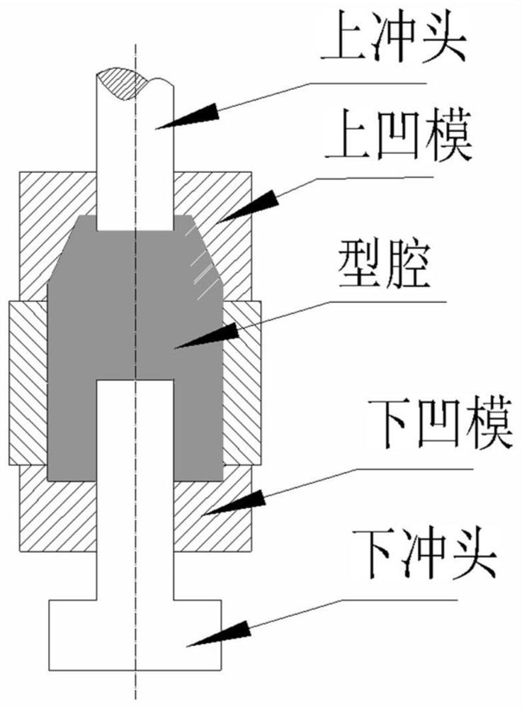
[0041] The use of induction heating equipment will be as figure 1 The upper and lower dies of the follow-up cavity shown are heated to 400°C and held for 30 minutes;

[0042] Step 4. Loading

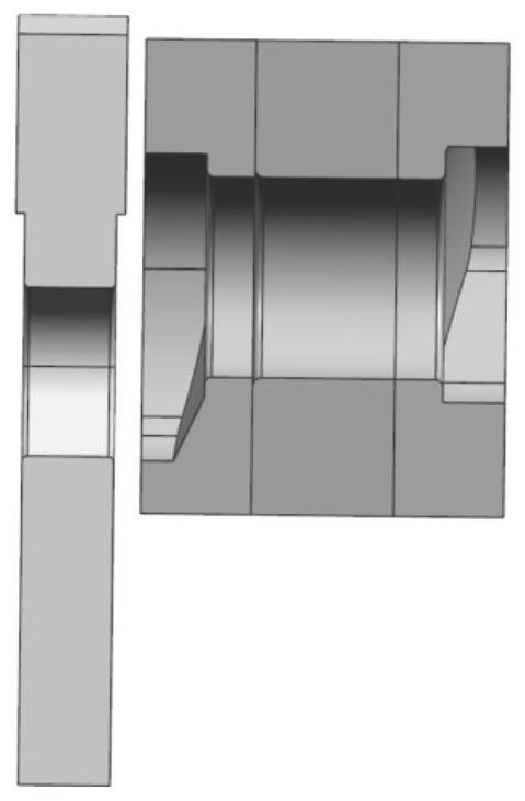
[0043] Put the blank heated in step 2 into such as figure 1 In the mold cavity of the follow-up cavity shown, the follow-up cavity includes an upper punch 1, an upper die 2, a cavity 3, a lower die 4 and a lower punch 5 arranged vertically in sequence;

[0044] Step five, close the mold

[0045] After step 4 is completed, the mold is...

Embodiment 2

[0085] A plastic forming method of non-proportional pressure loading of a 7A04 aluminum alloy support body with a reciprocating ejection die, the specific steps are as follows:

[0086] Step one, cutting

[0087] Will The 7A04 aluminum alloy bar stock sawing is of blanks.

[0088] Step 2. Heating

[0089] The billet completed in the first step is heated in a gas furnace to the initial forging temperature of 430°C.

[0090] Step three, mold heating

[0091] The use of induction heating equipment will be as figure 1 The upper and lower dies of the follow-up cavity shown are heated to 400°C and held for 30 minutes;

[0092] Step 4. Loading

[0093] Put the blank heated in step 2 into such as figure 1 In the cavity 3 of the follow-up cavity shown in the figure, the follow-up cavity includes an upper punch 1, an upper die 2, a cavity 3, a lower die 4 and a lower punch 5 arranged vertically in sequence;

[0094] Step five, close the mold

[0095] After step 4 is complete...


PUM


Abstract

The invention belongs to the technical field of manufacturing of specific metal articles, and particularly relates to a plastic forming method for a large complex special-shaped structural part. The plastic forming method sequentially comprises the procedures of discharging, blank heating, feeding, die assembly and reciprocating ejection extrusion, and is characterized in that the feeding comprises the following steps that a heated blank is put into a cavity of a follow-up cavity, and the follow-up cavity comprises an upper punch, an upper female die, a cavity body, a lower female die and a lower punch which are sequentially arranged. According to the method of the invention, the problem that the service life of a die is short in extrusion forming of a complex component can be solved; andthe plastic fluidity of a large complex special-shaped component can be remarkably improved, and the mold filling problem of the complex component is solved.

Description

technical field [0001] The invention belongs to the technical field of manufacturing specific metal objects, and in particular relates to a plastic forming method for large complex special-shaped structural parts. Background technique [0002] Large and complex special-shaped structural parts are one of the commonly used parts in engineering. They are widely used in various load-bearing structures, with high performance requirements and difficult processing. [0003] At present, the traditional manufacturing process of large complex special-shaped components is machining after die forging. However, the shape of large and complex special-shaped components is complex, and it is often necessary to design multiple billet-making processes, resulting in large machining allowances and serious cutting of metal flow lines; and the forming force is large, the forming temperature is high, and the load of the mold is poor, resulting in the life of the mold. Extremely low. [0004] At ...

Claims


Application Information

Patent Timeline
Patent Type & Authority Applications(China)
IPC IPC(8): B21C23/18B21C25/02B21C29/04B21J1/06B21J5/02
CPCB21C23/18B21C25/02B21C29/04B21J5/02B21J1/06
Inventor 康凤陈文赵祖德林军夏祥生陈驰舒大禹黄树海
Owner NO 59 RES INST OF CHINA ORDNANCE IND
Why Eureka
Try Eureka