A core tube concrete wall folding formwork and its application method

A technology of concrete wall and core tube, applied in the direction of formwork/formwork member, formwork/formwork/work frame, formwork/formwork/work frame connection, etc. Reasonable path, improve construction efficiency, and improve the effect of industrialization level

Active Publication Date: 2022-04-19
SHANGHAI CONSTRUCTION GROUP +1
View PDF16 Cites 0 Cited by
  • Summary
  • Abstract
  • Description
  • Claims
  • Application Information

AI Technical Summary

Problems solved by technology

[0004] Aiming at the problems that the large formwork of the concrete wall of the core tube of the building has a large amount of work in setting up the formwork and withdrawing the formwork, the present invention provides a folding formwork for the concrete wall of the core tube and its use method, which can realize the integral formwork of the large formwork , The overall demoulding, greatly reducing the workload of large formwork and demoulding, greatly improving work efficiency

Method used


Image

  • A core tube concrete wall folding formwork and its application method
  • A core tube concrete wall folding formwork and its application method
  • A core tube concrete wall folding formwork and its application method

Examples


Embodiment 1

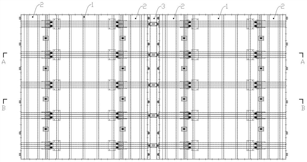
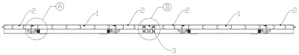
[0060] Such as Figure 1 to Figure 3 and Figure 16 and Figure 17 As shown, a core tube concrete wall folding formwork provided in this embodiment includes several flat forms 1 , rotary forms 2 , joint forms 3 and formwork push-pull devices 4 . A flat mold 1 and rotary molds 2 arranged on both sides of the flat mold form a group of opening and closing mold units, and the flat mold is hinged to the rotary molds on both sides; two groups of adjacent opening and closing mold units are connected by a joint mold 3, The joint mold is hinged with the rotary molds on both sides.

[0061] The template push-pull device 4 includes a telescopic end, and the telescopic end is fixedly connected to the back of the flat mold 1. The template push-pull device 4 is used to drive the flat mold 1 to reciprocate perpendicular to the wall surface 5, and the flat mold 4 drives the rotary mold 2 Rotate and move with the flat mold, the rotary mold 2 on both sides drives the joint mold 3 to approach...

Embodiment 2

[0070] This embodiment provides a method for using the folded formwork for the concrete wall of the core tube. Figure 1 to Figure 19 The method of use is further described. The method of use includes the following steps:

[0071] S1. Set the formwork push-pull device on the formwork; after the wall reinforcement binding of the building structure is completed, set a number of flat forms, rotary forms and continuous forms on both sides of the wall, two rotary forms and a flat form form a set of opening The mold clamping unit, the two opening and closing mold units are connected through the joint mold, and the flat mold is connected with the template push-pull device to form an overall folded template; all the template push-pull devices connected with the flat mold work together, and the telescopic rod is stretched out and Push the folding template to be in the mold closing state, such as Figure 18 shown.

[0072] Specifically, the connecting plate of the rotating shaft of the...


PUM


Abstract

The invention discloses a core-tube concrete wall folding formwork and a use method thereof. The core-tube concrete wall folding formwork includes several flat forms, rotating forms, continuous forms and formwork push-pull devices; a flat form and the rotating forms arranged on both sides of the flat form form a set of opening and closing units, and the flat form and the two sides of the flat form The rotating die is hinged; the two groups of adjacent opening and closing die units are connected by a continuous die, and the continuous die is hinged with the rotating die on both sides; the template push-pull device includes a telescopic end, and the telescopic end is fixedly connected to the back of the flat die. The formwork push-pull device is used to drive the flat form to reciprocate perpendicular to the wall, the flat form drives the rotary die to rotate, and the rotary die on both sides drives the continuous die to move closer to or away from the wall, so as to realize the clamping of the core-tube concrete wall folding formwork. , withdraw the mold. The folding template can realize fast and integrated mold clamping and mold release of the overall template structure, greatly reducing the workload of large template erection and mold removal, and greatly improving work efficiency.

Description

technical field [0001] The invention relates to a core tube concrete wall folding formwork and a use method thereof, belonging to the technical field of formwork in building construction. Background technique [0002] During the construction of high-rise and super high-rise buildings, the vertical structure of the cast-in-place concrete core tube is often constructed using climbing formwork. The climbing formwork is attached to the concrete structure that has been poured, and can climb upwards with the construction progress of the vertical structure of the core tube. A large formwork is set on the climbing formwork as a cast-in-place concrete forming mold. [0003] In the traditional process, the opening and closing operations of large templates are all done manually, which consumes a lot of labor costs. By setting up an automatic opening and closing system on the climbing frame, the automatic opening and closing of large templates can be realized through push-pull devices s...

Claims


Application Information

Patent Timeline
IPC IPC(8): E04G11/28E04G9/08E04G11/08E04G17/00E04G17/04
CPCE04G11/28E04G9/08E04G11/08E04G11/085E04G17/00E04G17/04
Inventor 潘曦黄玉林赵挺生左自波张龙龙占羿箭
Owner SHANGHAI CONSTRUCTION GROUP
Why Eureka
Try Eureka