Installation plate structure, air duct structure and air conditioner indoor unit

A technology for installing panels and air ducts, applied in air conditioning systems, mechanical equipment, machines/engines, etc., can solve problems such as small air volume, achieve the effects of increasing air volume, reducing eddy current loss, and improving fan efficiency

Pending Publication Date: 2021-02-02
GREE ELECTRIC APPLIANCES INC
View PDF0 Cites 0 Cited by
  • Summary
  • Abstract
  • Description
  • Claims
  • Application Information

AI Technical Summary

Problems solved by technology

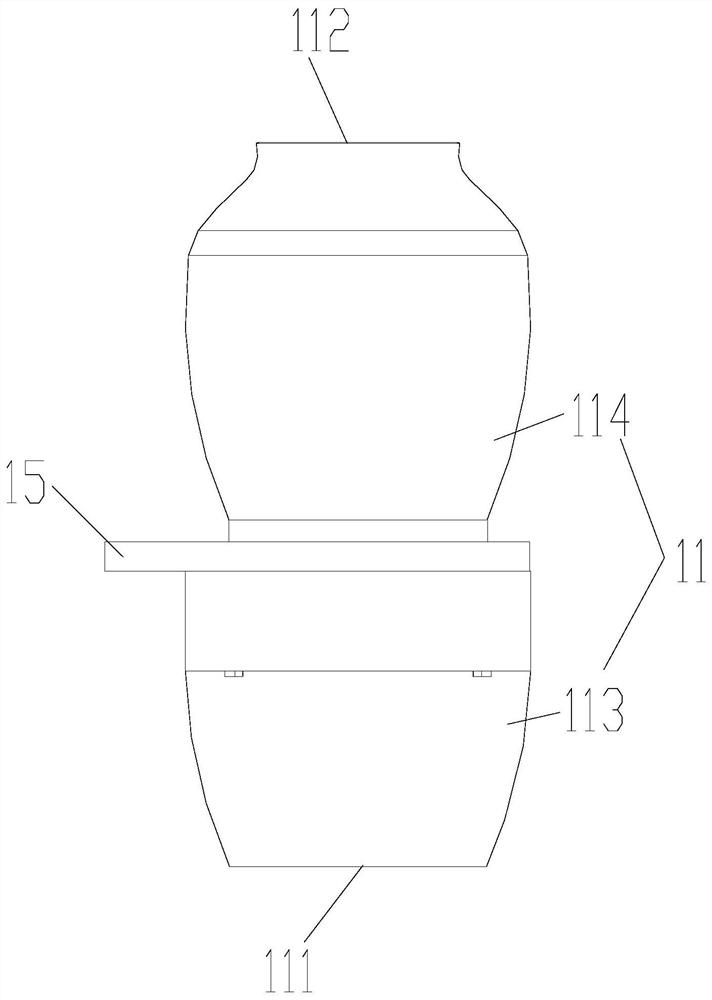
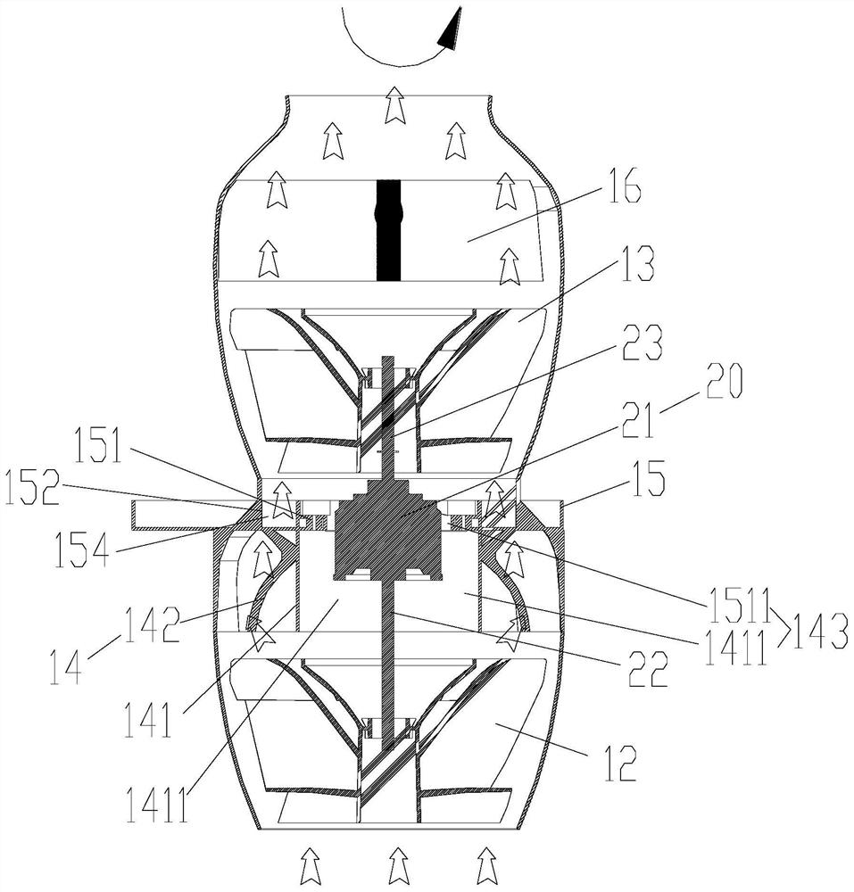
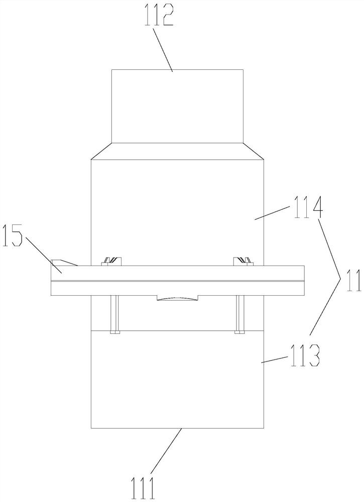
[0005] The main purpose of the present invention is to provide a mounting plate structure, an air duct structure and an air conditioner indoor unit, so as to solve the problem that the air output of the air duct structure in the prior art is small

Method used


Image

  • Installation plate structure, air duct structure and air conditioner indoor unit
  • Installation plate structure, air duct structure and air conditioner indoor unit
  • Installation plate structure, air duct structure and air conditioner indoor unit

Examples


Embodiment Construction

[0040] It should be noted that, in the case of no conflict, the embodiments in the present application and the features in the embodiments can be combined with each other. The present invention will be described in detail below with reference to the accompanying drawings and examples.

[0041] It should be pointed out that the following detailed description is exemplary and intended to provide further explanation to the present application. Unless defined otherwise, all technical and scientific terms used herein have the same meaning as commonly understood by one of ordinary skill in the art to which this application belongs.

[0042]It should be noted that the terminology used here is only for describing specific implementations, and is not intended to limit the exemplary implementations according to the present application. As used herein, unless the context clearly dictates otherwise, the singular is intended to include the plural, and it should also be understood that whe...


PUM


Abstract

The invention provides an installation plate structure, an air duct structure and an air conditioner indoor unit. At least part of the installation plate structure is located in an air duct, the installation plate structure comprises an installation plate main body and a first-stage guide vane, wherein an installation part used for installing a driving device is arranged on the installation platemain body and located in the air duct, and the first-stage guide vane is arranged on the installation plate main body, and the first-stage guide vane is located in the air duct so as to adjust airflowlocated in the air duct through the first-stage guide vane. According to the installation plate structure, the air duct structure and the air conditioner indoor unit, the problem that in the prior art, the air outlet amount of an air duct structure is smaller is solved.

Description

technical field [0001] The invention relates to the technical field of household appliances, in particular to a mounting plate structure, an air duct structure and an air conditioner indoor unit. Background technique [0002] In order to improve the energy utilization rate of the air conditioner and improve the comfort of the human body, different air outlet methods are required in different modes. In the cooling mode, cold air is blown from the top to achieve a shower-like cooling effect; in the heating mode, hot air is blown from the bottom to achieve a carpet-like heating effect. Shower cooling and carpet heating can make more efficient use of the properties of the gas itself and achieve higher energy utilization. [0003] At present, there are three types of fan blades widely used in air conditioners on the market: centrifugal fan blades, cross-flow fan blades and axial flow fan blades. For different usage requirements and air inlet and outlet methods, different fan bla...

Claims


Application Information

Patent Timeline
IPC IPC(8): F04D29/60F04D29/40F04D29/26F24F1/0033
CPCF04D29/26F04D29/403F04D29/601F24F1/0033
Inventor 董明珠王千千陈诚何振健吴晓岳戴志炜
Owner GREE ELECTRIC APPLIANCES INC
Why Eureka
Try Eureka