A mechanical vibration-electric energy conversion device with integrated mechanical rectification mechanism

A technology of mechanical rectification and mechanical vibration, applied in electromechanical devices, transmission devices, control of mechanical energy, etc., can solve problems such as low reliability, aggravated wear, and screw bending, so as to improve energy utilization and reliability, and improve power generation. Efficiency and saving installation space

Active Publication Date: 2019-07-26
奇瑞新能源汽车股份有限公司
View PDF14 Cites 0 Cited by
  • Summary
  • Abstract
  • Description
  • Claims
  • Application Information

AI Technical Summary

Problems solved by technology

[0004] Although the transmission efficiency of the rack and pinion mechanism is high, due to the unavoidable backlash between the gear and the rack, when the rack is subjected to a momentary impact of a large load, the tooth surface of the gear and the rack will be subjected to a large force. The strength of the tooth root is a great test, and at the same time it increases wear and tear, causing problems such as low reliability, high noise, and poor precision;
[0005] Although the ball screw mechanism can eliminate the gap through pre-tightening, and has low noise and high precision, the thread pitch of the ordinary ball screw is small. waste, the screw may be bent or even broken in severe cases
[0006] In addition to the above shortcomings, since the vibration is reciprocating, when the vibration direction of the rack and pinion mechanism or the ball screw mechanism changes, the gear or nut will also move in the opposite direction, driving the generator to rotate in the opposite direction, causing a large reaction. To the impact

Method used


Image

  • A mechanical vibration-electric energy conversion device with integrated mechanical rectification mechanism
  • A mechanical vibration-electric energy conversion device with integrated mechanical rectification mechanism
  • A mechanical vibration-electric energy conversion device with integrated mechanical rectification mechanism

Examples


Embodiment Construction

[0035] The specific implementation of the mechanical vibration-electric energy conversion device integrated with the mechanical rectification mechanism of the present invention will be described in detail below with reference to the accompanying drawings.

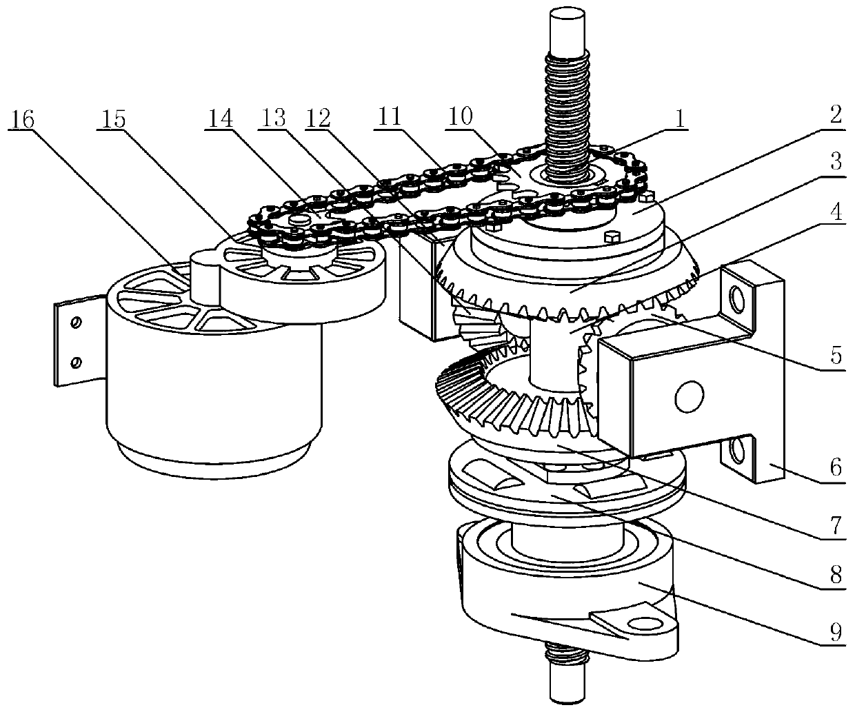
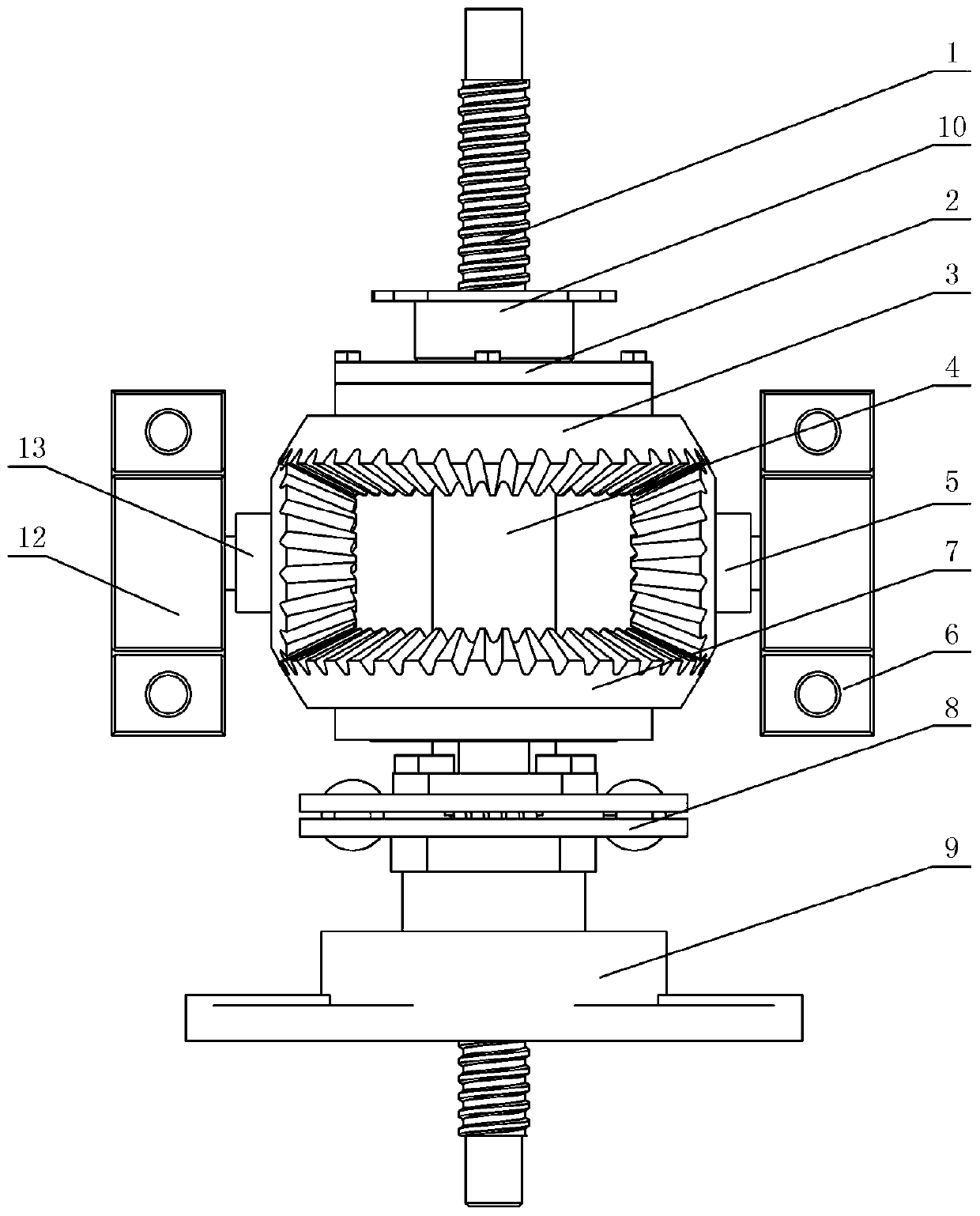
[0036] Please refer to figure 1 and figure 2 , the mechanical vibration-electric energy conversion device of the integrated mechanical rectification mechanism of this embodiment, its structure is specifically:

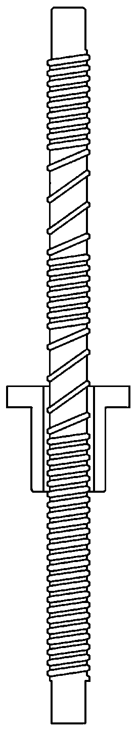
[0037] A motion conversion mechanism is provided to convert the linear motion of mechanical vibration into rotational motion, which is: the top end of the nut of the ball screw pair supported by the first bearing passes through the torsional shock absorber 8 and the connecting sleeve 4 of the mechanical rectification mechanism The bottom end is coaxial and fixedly connected, and the up and down movement of the screw 1 caused by vibration is converted into the bidirectional rotational movement of the nut through th...


PUM


Abstract

The invention provides a mechanical vibration-electric energy conversion apparatus integrated with a mechanical rectifying mechanism. The mechanical vibration-electric energy conversion apparatus consists of a movement conversion mechanism, the mechanical rectifying mechanism and a power generation mechanism; the movement conversion mechanism is used for converting linear movement of mechanical vibration into rotary movement; the mechanical rectifying mechanism is used for rectifying the bidirectional rotary movement into fixed direction rotary movement and outputting the fixed direction rotary movement to the power generation mechanism; and the power generation mechanism is used for converting the fixed direction rotary movement into electric energy. By virtue of the mechanical vibration-electric energy conversion apparatus, energy in going up and going down processes of vibration can be utilized fully, and reliability and power generation efficiency of the apparatus in high-load instantaneous impact of the apparatus can be improved.

Description

technical field [0001] The invention relates to a mechanical vibration-electric energy conversion device integrating a mechanical rectification mechanism. Background technique [0002] Vibration and shock are ubiquitous in nature, and in most cases, the energy generated by vibration is eventually turned into useless work and wasted. If the energy generated by vibration can be efficiently recycled, it will help reduce the use of fossil fuels and the environment. pollution. [0003] The existing products mainly use rack and pinion or ball screw to convert the linear motion of mechanical vibration into the rotational motion of the generator, so as to realize the recovery of vibration energy and power generation. However, both of the above mechanisms have disadvantages: [0004] Although the transmission efficiency of the rack and pinion mechanism is high, due to the unavoidable backlash between the gear and the rack, when the rack is subjected to an instantaneous impact of a ...

Claims


Application Information

Patent Timeline
Patent Type & Authority Patents(China)
IPC IPC(8): H02K7/18H02K7/06F16H37/12H02K5/24
CPCF16H37/12H02K5/24H02K7/06H02K7/1807
Inventor 白先旭钟伟民邓学才祝安定王金桥王经常
Owner 奇瑞新能源汽车股份有限公司
Why Eureka
Try Eureka