
Grading vibration reduction device based on magnetic force
A vibration damping device and magnetic force technology, applied in the direction of spring/shock absorber, vibration suppression adjustment, mechanical equipment, etc., can solve problems such as speeding up the replacement cycle of parts, affecting the quality of plate and strip products, and affecting the life of drive shafts, etc., to achieve Good development space and market prospect, compact structure, improved inhibition effect
- Summary
- Abstract
- Description
- Claims
- Application Information
AI Technical Summary
Problems solved by technology
Method used
Image

Examples
Embodiment 1
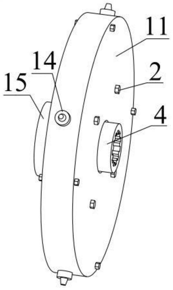
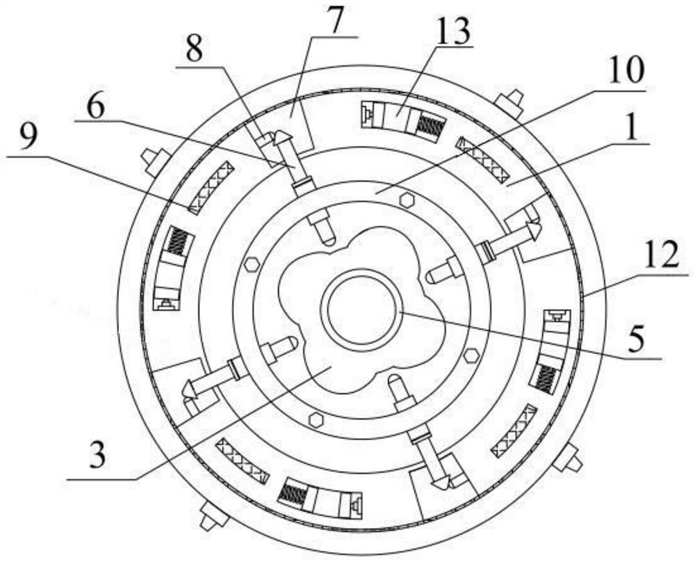
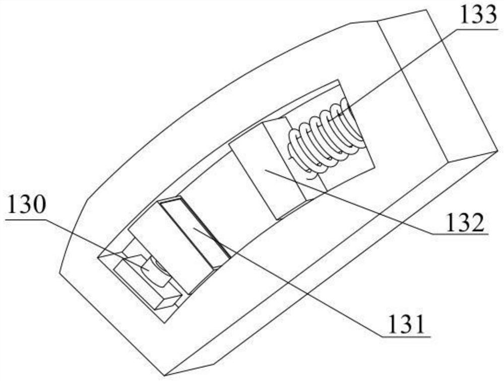
[0025] Such as figure 1 and figure 2 As shown, the grading damping device based on magnetic force includes an annular connecting disc 1, a central disc 3, an annular support 10 and a spline shaft 4; the spline shaft and the central disc are connected as a whole by interference fit; The bracket is located on the periphery of the central disk, and the annular connecting plate is located on the periphery of the annular support; inside the annular connecting plate are provided with 4 cavities 7, 4 damping windows 13 and 4 annular lubricating oil grooves 9; on the annular support 4 spring push rods 6 are also fixedly installed, one end of the spring push rod extends into the cavity, and the other end of the spring push rod contacts the central disc; and spring push rods are all arranged around the center of the annular connecting disc at equal distances; wherein, the annular connecting disc, the central disc and the annular support are all symmetrical structures. The splined sha...
PUM
 Abstract
Description
Claims
Application Information