
Automatic grinding machine for automobile shifting fork

A grinding machine and automatic technology, which is applied in the direction of grinding frame, grinding machine parts, grinding bed, etc., can solve the problem that automatic loading and unloading cannot be achieved

Active Publication Date: 2018-09-28
南理工泰兴智能制造研究院有限公司
View PDF6 Cites 15 Cited by
  • Summary
  • Abstract
  • Description
  • Claims
  • Application Information

AI Technical Summary

Problems solved by technology

[0003] Chinese Patent No. CN201410611904.8 is a double-plane integrated processing equipment for a reverse gear fork, including a stand, a tooling bottom plate, a support block, a left vertical plate, and a right vertical plate. When the right positioning block extends into the fork of the reverse gear fork, the ejector rod of the middle vertical cylinder stretches upwards and just supports the lower end surface of the reverse gear shift fork, and the ejector rod of the right vertical cylinder extends upwards just right It is supported on the waist of the reverse gear fork; when the reverse gear fork rotates 180° counterclockwise, the round hole of the reverse gear fork is placed on the left set cylinder, and the left positioning block extends into the fork of the reverse gear fork. When the left support block is supported under the upper end surface of the reverse gear fork, the ejector rod of the left vertical cylinder stretches out upwards and just supports the waist of the reverse gear fork. Between the plates, the two end faces of the shift fork can be polished, but the functions such as automatic loading and unloading cannot be achieved.

Method used


Image

  • Automatic grinding machine for automobile shifting fork
  • Automatic grinding machine for automobile shifting fork
  • Automatic grinding machine for automobile shifting fork

Examples


Embodiment Construction

[0035] Below in conjunction with accompanying drawing and embodiment of description, specific embodiment of the present invention is described in further detail:

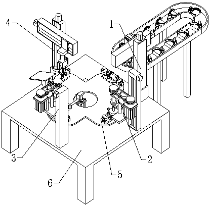
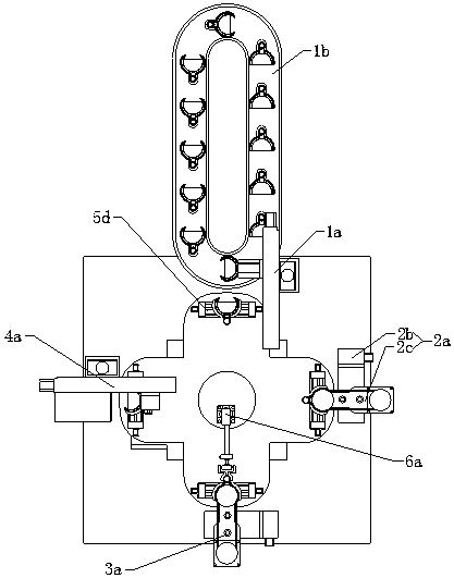
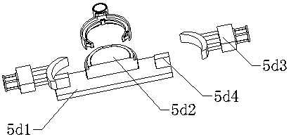
[0036] refer to Figure 1 to Figure 10The shown automatic grinding machine for an automobile shift fork includes a base 6, and also includes a loading station 1, a first grinding station 2, a second grinding station 3, an unloading station 4 and Rotary table 5, described rotary table 5 includes indexing plate 5a, stepping motor 5b and fixture mounting table 5c, on the fixed mounting base 6 of described indexing plate 5a, the distance between indexing plate 5a and stepping motor 5b The output end is connected, and the fixture installation platform 5c is horizontally arranged on the indexing plate 5a. There is also a round hole at the center of the fixture installation platform 5c. Four workpiece fixtures for holding and clamping the workpiece are arranged on the fixture installation platform 5c. 5d, the loading stat...


PUM


Abstract

The invention relates to the field of automobile part machining, in particular to an automatic grinding machine for an automobile shifting fork. The automatic grinding machine comprises a base and further comprises a feeding station, a first grinding station, a second grinding station, a discharging station and a rotating workbench; the rotating workbench comprises a fixture installing table, thefixture installing table is horizontally arranged on an index plate and provided with four workpiece fixtures used for containing and clamping workpieces, and the feeding station, the first grinding station, the second grinding station and the discharging station are clockwise and sequentially arranged along the periphery of the fixture installing table and correspond to the workpiece fixtures arranged on the fixture installing table one to one in a working state; the feeding station comprises a feeding mechanical arm used for putting the workpieces on the workpiece fixtures; the first grinding station comprises a first grinding mechanism used for grinding the workpieces; the second grinding station comprises a second grinding mechanism used for grinding the workpieces; and the dischargingstation comprises a discharging mechanical arm. Therefore, the problems that the human cost input is high, and the yield is low are solved.

Description

technical field [0001] The invention relates to the field of automobile parts processing, in particular to an automatic grinding machine for an automobile shift fork. Background technique [0002] The shift fork is a part of the car gearbox. It is connected to the shift handle and is located at the lower end of the handle. The middle shift wheel is moved to change the input / output speed ratio. The shift fork is mainly used for clutch shifting. It is to separate the two meshed gears and then switch one of the gears that can slide on the shaft to the other gear to obtain another speed, that is, to change the position of the slipping gear of the lathe to achieve speed change, or to control the clutch With the development of the automobile industry, especially the research and development of new energy-saving and environmentally friendly vehicles, it is a challenge and an opportunity for auto parts, especially the weight of commercial vehicles. The weight of each component must...

Claims


Application Information

Patent Timeline
IPC IPC(8): B24B27/00B24B41/06B24B41/02B24B41/00
Inventor 唐伟金卫明
Owner 南理工泰兴智能制造研究院有限公司
Learn More