
A Soil Automatic Sampling Mechanism for Engineering Survey Based on Magnetic Control
A technology of magnetic control and automatic sampling, applied in sampling devices and other directions, can solve the problems of time-consuming, labor-intensive, complicated operation, etc., and achieve the effect of convenient use and simple structure.
- Summary
- Abstract
- Description
- Claims
- Application Information
AI Technical Summary
Problems solved by technology
Method used
Image

Examples
Embodiment
[0027] as attached figure 1 to attach Figure 4 Shown:
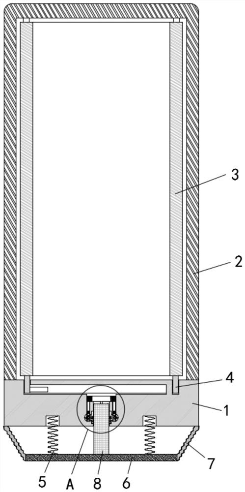
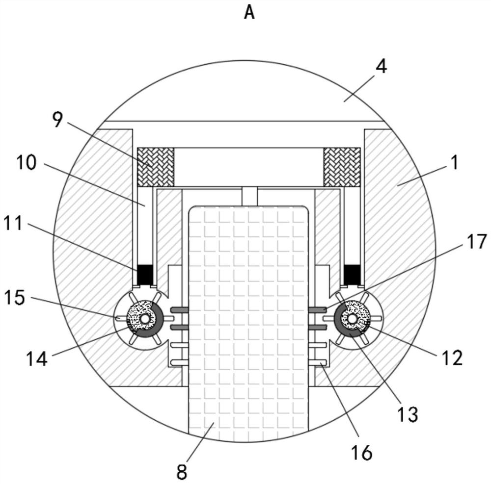
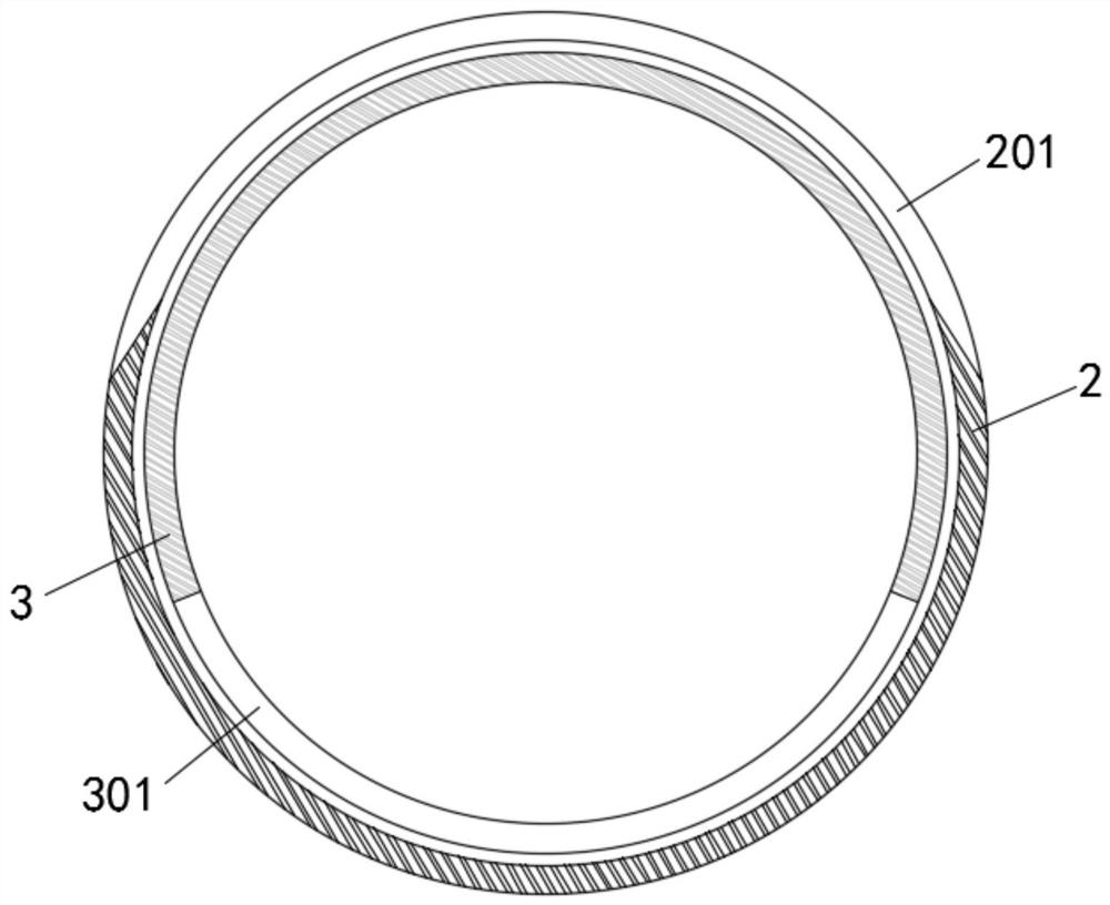
[0028] The present invention provides a soil automatic sampling mechanism for engineering survey based on magnetic force control, comprising a base 1, the top of the base 1 is fixedly connected with an outer cylinder 2, the side wall of the outer cylinder 2 is provided with a sampling port 201, the top of the base 1 is The inner cylinder 3 is rotatably connected to the inside of the outer cylinder 2. There is a gap 301 on the side wall of the inner cylinder 3. The inner cylinder 3 is installed on the base 1 through the support ring 4. The bottom of the base 1 is connected to the detection plate through the compression spring 5. 6. The outside of the detection board 6 is covered with an elastic protective layer 7 connected to the base 1. The top of the detection board 6 is fixedly connected with a guide post 8 inserted into the base 1. The inside of the base 1 slides above the guide post 8 A lifting ring 9 is plugged in...
PUM
 Abstract
Description
Claims
Application Information