Friction machine

A technology of friction machine and friction roller, which is applied in the field of friction machine and can solve the problems of affecting friction quality and insufficient rigidity of the system

Pending Publication Date: 2021-02-02
深圳市晶向科技有限公司
View PDF0 Cites 3 Cited by
  • Summary
  • Abstract
  • Description
  • Claims
  • Application Information

AI Technical Summary

Problems solved by technology

[0008] In view of the deficiencies of the above-mentioned prior art, the purpose of the present invention is to provide a friction machine to solve the problem that the rigidity of the e

Method used


Image

  • Friction machine

Examples


Embodiment Construction

[0016] The invention provides a friction machine. In order to make the purpose, technical solutions and effects of the present invention clearer and clearer, the present invention will be further described in detail below with reference to the accompanying drawings and examples. It should be understood that the specific embodiments described here are only used to explain the present invention, not to limit the present invention.

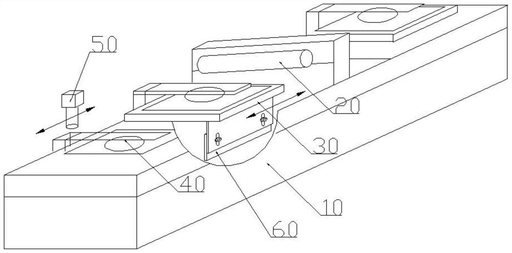
[0017] see figure 1 , figure 1 It is a structural schematic diagram of the friction machine provided by the present invention. As shown in the figure, the friction machine includes a frame 10 , a friction roller 20 , a working platform 30 and a first manipulator 40 . Described rubbing roller 20, work platform 30 are arranged on the frame 10, and described first manipulator 40 is arranged on the side of work platform 30.

[0018] Specifically, the working platform 30 is used to place a workpiece (i.e. a glass substrate), and the rubbing roller 20 ...


PUM


Abstract

The invention discloses a friction machine for rubbing a glass substrate. The friction machine comprises a rack, a friction roller, a working platform, a first manipulator and a visual image recognition device, wherein the friction roller and the working platform are arranged on the rack; the first manipulator is arranged on one side of the working platform; and the first manipulator is used for rotating the glass substrate by a preset angle and placing the workpiece on the working platform according to the preset angle. When the working platform and the friction roller work, a workpiece is kept fixed, the rigidity of the system is improved, and therefore friction is ensured to be evenly conducted in the same direction during friction.

Description

technical field [0001] The invention relates to the technical field of manufacturing liquid crystal display elements, in particular to a rubbing machine equipped with a manipulator. Background technique [0002] With the rapid economic development, liquid crystal products are widely used in all aspects of life, and the production scale of liquid crystal panels is also expanding day by day. [0003] The liquid crystal panel generally includes two glass substrates, on the inner surfaces of the two glass substrates, transparent electrodes for applying an electric field to the liquid crystal layer are provided, switching elements are provided for controlling the ON-OFF of the electric field, and a color film can be provided for displaying colors, and In order to align the liquid crystal molecules, various parts such as an alignment film are provided. The so-called alignment film is formed by materials such as glass mitt coated on the glass substrate. After the alignment film is...

Claims


Application Information

Patent Timeline
IPC IPC(8): G02F1/1337
CPCG02F1/133784
Inventor 安峰
Owner 深圳市晶向科技有限公司
Why Eureka
Try Eureka