Supercharge Your Innovation With Domain-Expert AI Agents!

Magnetic type electric connector of manufacturing process

A process technology and technology of electrical connectors, applied in the direction of connecting and connecting parts of devices, devices for joining/disconnecting connected parts, etc., can solve the problem that electrical connections are easy to be pulled or dragged, electrical connectors cannot work normally, Difficult to deal with pulling, dragging and other problems, to achieve the effect of increasing contact guide effect, simple structure and convenient insertion

Inactive Publication Date: 2021-02-02
李成保
View PDF5 Cites 0 Cited by
  • Summary
  • Abstract
  • Description
  • Claims
  • Application Information

AI Technical Summary

Problems solved by technology

[0005] In view of the above-mentioned shortcomings existing in the prior art, the present invention provides a magnetic suction electrical connector with a manufacturing process, which can effectively solve the problem that the electrical connection in the prior art is easy to be pulled or dragged. If only relying on contact friction force, it is difficult to To deal with the situation of pulling and dragging, it is easy to cause the electrical connector to loosen and fall off, so that the electrical connector cannot work normally

Method used


Image

  • Magnetic type electric connector of manufacturing process
  • Magnetic type electric connector of manufacturing process
  • Magnetic type electric connector of manufacturing process

Examples


Embodiment

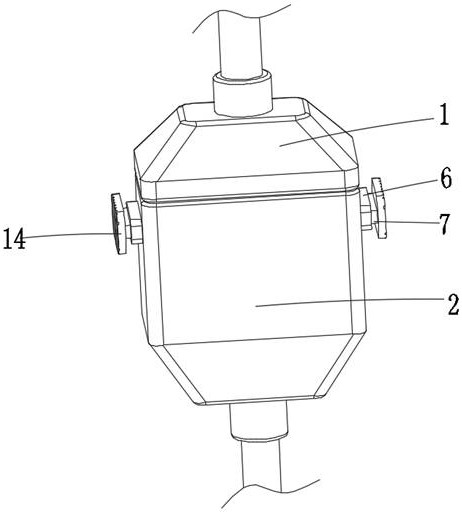
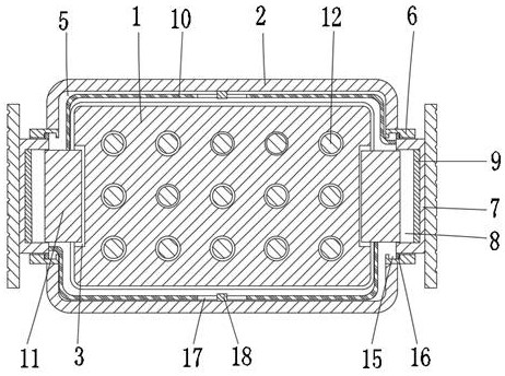
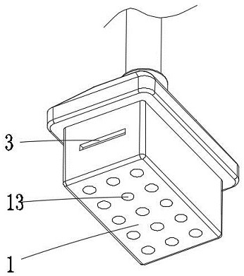
[0031] The magnetic suction type electric connector of a kind of manufacturing process technology of this embodiment, refer to Figure 1-4 : Including the male plug 1 and the female plug 2, the left and right sides of the male plug 1 are provided with a magnetically conductive metal groove 3, the upper side of the female plug 2 is provided with a slot 4, the inner wall of the middle part of the slot 4 is provided with an annular groove 5, and the female plug 2 The upper part is provided with protrusions 6 on the left and right sides, and the middle part of the protrusions 6 is provided with a sliding port which communicates with the annular groove 5, and a guide slider 7 is slidably connected in the sliding port, and the guide slider 7 is provided with a concave groove on the side close to the slot 4. Groove 8, the inner wall of the groove 8 away from the slot 4 side is provided with a first magnetic block 9, and the side of the guide slider 7 close to the slot 4 is fixedly con...


PUM


Abstract

The invention relates to the field of electric connectors, in particular to a magnetic type electric connector of a manufacturing process, which comprises a male plug and a female plug, magnetic conductive metal grooves are formed in the left and right sides of the male plug, a slot is formed in the upper side of the female plug, an annular groove is formed in the inner side wall of the middle ofthe slot, and protruding blocks are arranged on the left and right sides of the upper part of the female plug; sliding openings communicating with the annular grooves are formed in the middles of theprotruding blocks, guiding sliding blocks are slidably connected into the sliding openings, grooves are formed in the sides, close to the slot, of the guiding sliding blocks, first magnetic blocks arearranged on the inner walls of the sides, away from the slot, of the grooves, connecting pieces are fixedly connected to the sides, close to the slot, of the guiding sliding blocks, and the two connecting pieces are symmetrically arranged in the annular groove. The structure is simple, the male plug can be inserted into or pulled out of the female plug only by pressing the two sets of pressing keys at the same time, the operation is easy, meanwhile, through the magnetic clamping of the magnetic conductive metal grooves and a second magnetic block, the connection stability of the male plug andthe female plug is improved, and the male plug and the female plug are not prone to loosening or falling off under the action of external force.

Description

technical field [0001] The invention relates to the field of electrical connectors, in particular to a magnetic suction type electrical connector with a manufacturing process. Background technique [0002] The manufacturing process, that is, the "manufacturing process" of the CPU, refers to the fineness of the integrated circuit in the process of producing the CPU. The higher the precision, the more advanced the production process. More electronic components can be manufactured in the same material, and the thinner the connecting wire, the higher the fineness, and the smaller the power consumption of the CPU. [0003] The existing electrical connectors include a male plug and a female plug. The male plug has a jack, and the female plug has a pin. When the male plug and the female plug are plugged together, the two are connected and fixed by the contact friction after plugging . In some environments, the electrical connection is easy to be pulled or dragged. If only relying...

Claims


Application Information

Patent Timeline
IPC IPC(8): H01R13/629H01R13/639H01R13/62H01R13/52H01R13/02H05K7/20
CPCH01R13/02H01R13/52H01R13/6205H01R13/629H01R13/639H05K7/2039
Inventor 李成保
Owner 李成保
Features
  • R&D
  • Intellectual Property
  • Life Sciences
  • Materials
  • Tech Scout
  • Unparalleled Data Quality
  • Higher Quality Content
  • 60% Fewer Hallucinations
Learn More