Network signal enhanced connection device for big data software
A network signal and strengthening connection technology, applied in the parts, connection, coupling device and other directions of the connection device, can solve the problems of the antenna pole shaking, inconvenient use, the network signal strengthening device falling off, etc., to avoid falling off and avoiding the effect of separation.
- Summary
- Abstract
- Description
- Claims
- Application Information
AI Technical Summary
Problems solved by technology
Method used
Image

Examples
Embodiment Construction
[0027] The following will clearly and completely describe the technical solutions in the embodiments of the present invention with reference to the accompanying drawings in the embodiments of the present invention. Obviously, the described embodiments are only some, not all, embodiments of the present invention.
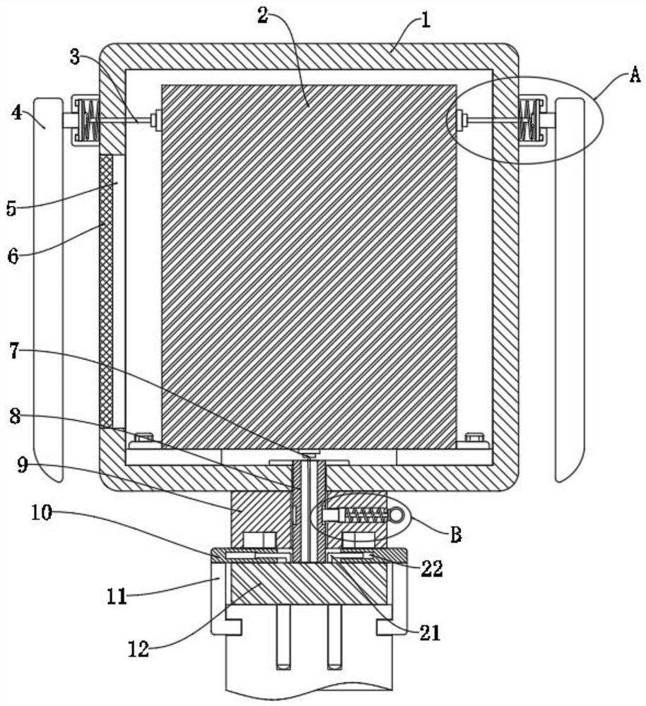
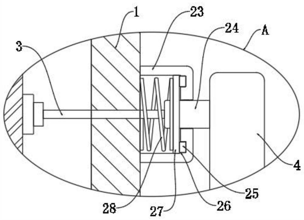
[0028] refer to Figure 1-7 , a network signal strengthening connection device for big data software, including a housing 1, a circuit module 2 is installed inside the housing 1, antenna mechanisms are provided on both side walls of the housing 1 near the upper part, and the antenna mechanism and the circuit The module 2 is connected, the bottom of the housing 1 is provided with a connecting pipe 8, and the connecting pipe 8 is connected to the housing 1 in rotation, the lower end of the connecting pipe 8 is fixedly connected with a plug 12, and the plug 12 is connected to the circuit module 2 through the second connecting wire 7. Connection, the connecting pipe 8 is...
PUM
 Abstract
Description
Claims
Application Information
PatSnap Eureka turns technology decisions into work you can execute. Powered by our Innovation Knowledge Graph, it runs expert workflows across engineering, life sciences, materials and intellectual property. Get your review-ready output in minutes.


