[0025] The following will clearly and completely describe the technical solutions in the embodiments of the present invention with reference to the accompanying drawings in the embodiments of the present invention. Obviously, the described embodiments are only some, not all, embodiments of the present invention. Based on the embodiments of the present invention, all other embodiments obtained by persons of ordinary skill in the art without making creative efforts belong to the protection scope of the present invention.
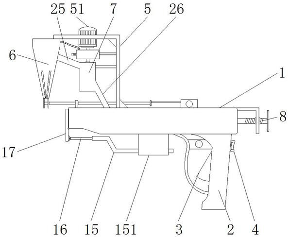
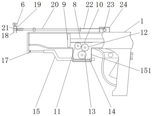
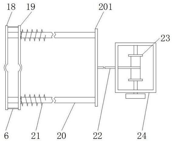
[0026] see Figure 1-7 , the present invention provides a technical solution: a hand-held pollination and pollination integrated machine for corn planting, including a pollination gun 1, a handle 2, a trigger key 3, a control button 4, a bracket 5, a motor 51, a motor shaft 52, Powder collection bag 6, delivery box 7, valve stem 8, valve plate 9, first tooth block 10, first gear 11, second gear 12, third gear 13, second tooth block 14, sleeve rod 15, control box 151, pull rod 16, baffle plate 17, movable plate 18, fixed plate 19, slide bar 20, pull plate 201, tension spring 21, stay cord 22, reel 23, line box 24, suction pipe 25, blowpipe 26, fan Leaf 27, cam plate 28, blow box 29, pressing plate 30, guide bar 31, connecting spring 32, air bag 33, trachea 34, air chamber 35 and air hole 36, the bottom end of pollination gun 1 is equipped with handle 2, and handle 2 Trigger key 3 and control button 4 are installed on it, and control button 4 is electrically connected with motor 51, and motor 51 is installed on the bracket 5, and the bottom end of bracket 5 is fixed on the top of pollination gun 1, and motor 51 and vertical distribution The motor shaft 52 is connected, the left end of the bracket 5 is equipped with a powder collection bag 6, and the side of the powder collection bag 6 is provided with a delivery box 7, and the delivery box 7 is located on the right side of the powder collection bag 6, and the powder collection bag 6 is The opening is set downwards, a valve stem 8 is installed in the pollination gun 1, and a valve plate 9 is installed on the left end of the valve stem 8, and the valve plate 9 is horizontally slidably connected to the inside of the pollination gun 1, and the lower end surface of the valve stem 8 is provided with etc. The first tooth block 10 is distributed at a distance, and the first tooth block 10 is meshed with the first gear 11, and the first gear 11 and the third gear 13 are meshed with the second gear 12, and all three are installed in the control box 151 Inside, the control box 151 is installed on the lower end surface of the pollination gun 1, and the lower half of the control box 151 is horizontally connected to the right end of the sleeve rod 15, and the upper end surface of the sleeve rod 15 is equipped with a gear that meshes with the third gear 13. The second tooth block 14, the left end of the cover rod 15 is slidably connected with the right end of the spring and the pull rod 16 arranged inside, and the left end of the pull rod 16 is movably connected to the bottom end of the baffle plate 17, and the left end of the baffle plate 17 and the pollination gun 1 Hinged at opening.
[0027]Both sides of the bottom end of the powder collection bag 6 are respectively equipped with a movable plate 18 and a fixed plate 19, and the inner wall of the movable plate 18 is equipped with a horizontally distributed sliding rod 20, and the sliding rod 20 forms a sliding connection structure through the tension spring 21 and the fixed plate 19 , and the center of the fixed plate 19 and the movable plate 18 is a symmetrically distributed arc structure, the right end of the slide bar 20 is connected with the pull plate 201, and the outer surface of the pull plate 201 is fixedly connected with the left end of the stay rope 22, and the stay rope 22 The right end of the wire is wound and fixed on the winding wheel 23, and the winding wheel 23 is damped and rotated and installed inside the wire box 24, and the winding wheel 23 is connected with the knob on the surface of the wire box 24, and the male plant part of the corn plant is placed on the In the powder picking bag 6, the knob on the outside of the wire box 24 can then be manually rotated to drive the reel 23 to rotate accordingly, and the rotation of the reel 23 will drive the pull plate 201 to move to the right synchronously through the stay rope 22, and the slide bar 20 At this time, the movable plate 18 will be pulled to move to the right, so that the movable plate 18 and the fixed plate 19 will block the bottom opening of the powder sampling bag 6 from the bottom, and the middle arc of the movable plate 18 and the fixed plate 19 will The design of the structure can ensure that the male plant will not be broken and damaged, and then the user can manually shake the gun body to make the pollen on the male plant fall into the pollen bag 6 .
[0028] Suction pipe 25 and blowpipe 26 are installed respectively on the left and right sides of conveying box 7, and the top pollination bag 6 of suction pipe 25 is connected, and the bottom of blowpipe 26 is connected with the inside of pollination gun 1, and the inside of conveying box 7 is provided with The fan blade 27 installed on the bottom of the motor shaft 52, and the top of the delivery box 7 is provided with a blowing box 29. The user can control the operation of the motor 51 through the control button 4. When the motor 51 rotates clockwise, it will drive the motor shaft 52 and the fan. The leaves 27 rotate at a high speed synchronously, so the suction pipe 25, which acts as a negative pressure adsorption, will absorb the pollen in the pollen collection bag 6 into the suction pipe 25, and at the same time, under the conveying action of the delivery box 7, the pollen will enter into the suction pipe 26 via the blowpipe 26. The interior of pollination gun 1.
[0029] The inside of the blowing box 29 is provided with a cam plate 28, and the cam plate 28 and the motor shaft 52 are connected by a one-way bearing, and the side of the cam plate 28 is provided with a pressing plate 30, while the left side wall of the pressing plate 30 and the guide rod 31 is fixedly connected, and the guide rod 31 is slidably connected with the side wall of the connection spring 32 and the blow box 29, and the periphery of the guide rod 31 is distributed with an air bag 33 located inside the blow box 29, and the air bag 33 is located between the pressure plate 30 and the blow box. 29, the position between the left side walls, and the air bag 33 is an elastic structure, and the inside of the air bag 33 communicates with the bottom end of the air pipe 34, and the top end of the air pipe 34 communicates with the air cavity 35, and the air cavity 35 is opened in the powder sampling bag 6 Inside the side wall of the top, the air cavity 35 is connected with the air holes 36 distributed obliquely downward, and the air holes 36 are set in the inner wall of the pollen bag 6. After completing a single pollination operation, the user can control the motor 51 to drive Motor shaft 52 rotates counterclockwise, at this moment Figure 4 as well as Figure 5 The cam plate 28 in the center will rotate synchronously, so under the guidance of the surface structure of the cam plate 28, the pressure plate 30 will move to the left correspondingly, and produce a squeezing effect on the air bag 33. At this time, the air bag 33 rapidly deforms and shrinks. The air inside it will enter the inside of the air chamber 35 through the air pipe 34, and then spray out from the air hole 36, thereby recoil cleaning the pollen remaining in the pollen collection bag 6.
[0030] Working principle: When using the device, you can first hold the handle 2, and then figure 1 When the opening of the bottom end of the powder collection bag 6 shown is open, the male part of the corn plant is placed in the powder collection bag 6, and then the knob on the outside of the wire box 24 can be manually rotated to drive the winding wheel 23 to rotate accordingly. The rotation of wire pulley 23 can drive draw plate 201 to move to the right synchronously by stay rope 22, and slide bar 20 just can pull movable plate 18 to move to the right at this moment, makes movable plate 18 and fixed plate 19 pick up from the bottom. The bottom opening of the powder bag 6 is blocked, and the design of the middle arc structure of the movable plate 18 and the fixed plate 19 can ensure that the male plant will not be broken and damaged, and then the user can manually shake the gun body to make the The pollen on the male plant falls into the pollen collection bag 6, and the user can control the operation of the motor 51 through the control button 4. When the motor 51 rotates clockwise, it will drive the motor shaft 52 and the fan blade 27 to rotate at a high speed synchronously, thus playing a role The suction pipe 25 of the pressure adsorption function will absorb the pollen in the pollen collection bag 6 into the suction pipe 25, and at the same time, under the delivery action of the delivery box 7, the pollen will enter the inside of the pollination gun 1 through the blowpipe 26;
[0031] After the collection of pollen is completed, the user can directly press the trigger button 3, and the valve stem 8 will move to the left accordingly. When the valve stem 8 moves to the left, if figure 2 As shown, the first tooth block 10 will mesh with the first gear 11 to rotate, and then drive the third gear 13 to rotate together through the second gear 12. Under the meshing transmission effect of the third gear 13 and the second tooth block 14, the sleeve The bar 15 will rotate the baffle plate 17 counterclockwise through the pull rod 16, so that the muzzle is in an open state, and then the valve plate 9 continues to move, and pollen will be sprayed from the muzzle to the female plant that is aligned in advance, thereby Complete the pollination operation;
[0032] After completing a single pollination operation, the user can control the motor 51 to drive the motor shaft 52 to rotate counterclockwise. Figure 4 as well as Figure 5 The cam plate 28 in the center will rotate synchronously, so under the guidance of the surface structure of the cam plate 28, the pressure plate 30 will move to the left correspondingly, and produce a squeezing effect on the air bag 33. At this time, the air bag 33 rapidly deforms and shrinks. The air inside it will enter the inside of the air chamber 35 through the air pipe 34, and then spray out from the air hole 36, thereby recoil cleaning the pollen remaining in the pollen collection bag 6.
[0033] Although the embodiments of the present invention have been shown and described, those skilled in the art can understand that various changes, modifications and substitutions can be made to these embodiments without departing from the principle and spirit of the present invention. and modifications, the scope of the invention is defined by the appended claims and their equivalents.