Adjusting structure for device bearing area

A technology for adjusting structures and areas, which is applied in the field of adjusting structures, can solve the problems of low utilization rate of storage space and achieve the effect of improving utilization rate, stability of storage and flexibility of storage

Pending Publication Date: 2021-02-05
GUANGDONG DTC HARDWARE PRECISION MFG CO LTD
View PDF1 Cites 0 Cited by
  • Summary
  • Abstract
  • Description
  • Claims
  • Application Information

AI Technical Summary

Problems solved by technology

[0003] The purpose of the present invention is to provide an adjustment structure for the device receiving area to overcome the disadvantages of the prior ar

Method used


Image

  • Adjusting structure for device bearing area
  • Adjusting structure for device bearing area
  • Adjusting structure for device bearing area

Examples


no. 1 example

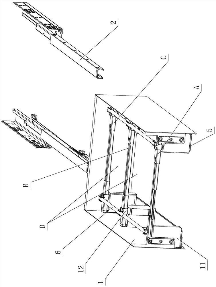
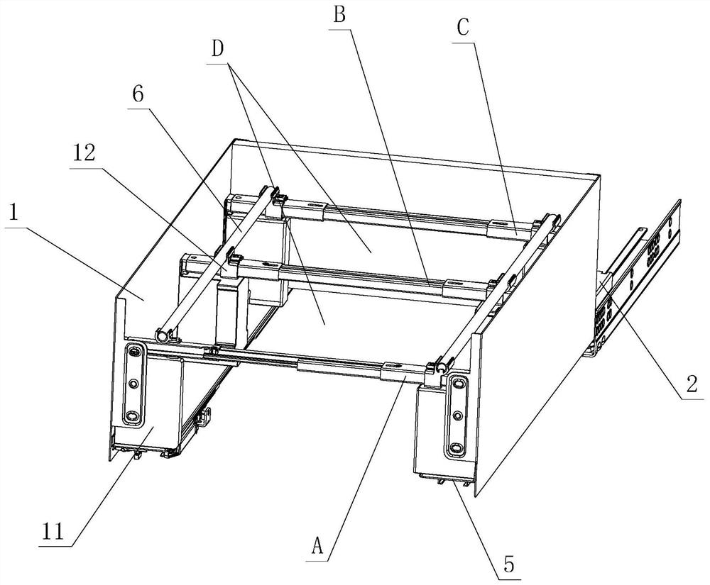
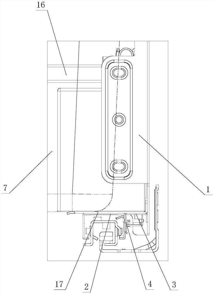
[0048] see Figure 1-Figure 15 , which is used for the adjustment structure of the device receiving area, including side plates 1 and slide rail assemblies 2 arranged on the left and right sides, the lower parts of the left and right side plates 1 are respectively provided with supporting parts 3, and the left and right supporting parts 3 are respectively provided with relying parts 4; The above-mentioned side plate 1 is detachably arranged on the slide rail assembly 2, and when the two are assembled, the slide rail assembly 2 leans against the inner side of the relying part 4.

[0049] A receiving device is arranged between the left and right supporting parts 3, and the receiving device includes a left and right base 5, and the left and right bases 5 are respectively supported on the left and right supporting parts 3 and / or the left and right slide rail assemblies 2, and at least Three cross-bar telescopic assemblies arranged in the front, middle and rear, and a vertical rod ...

no. 2 example

[0071] see Figure 16-Figure 25 , this adjustment structure for the device receiving area is different from the first embodiment in that: the middle movable rod 13 of the middle cross rod telescopic assembly B is provided with a bracket 20 .

[0072] The two movable parts 8 are respectively arranged on the bracket 20, and the two movable parts 8 are respectively provided with a positioning part 10 on both sides of the receiving area D; meanwhile, the two movable parts 8 are respectively provided with a rack and a convex part.

[0073] The adjusting part 9 is positioned and rotated on the bracket 20, and a gear part and an eccentric part are respectively arranged on it. The adjusting part 9 is driven and connected with the rack of one of the movable parts 8 through the gear part, and the adjusting part 9 is connected to the other through the eccentric part. The protrusions of a movable part 8 are drivingly connected to each other.

[0074] When the adjusting member 9 rotates, ...


PUM


Abstract

An adjusting structure for a device bearing area comprises a left side plate, a right side plate and a sliding rail assembly, and a supporting part and a leaning part are arranged on the lower portions of the left side plate and the right side plate respectively. The side plate is detachably arranged on the slide rail assembly, and the slide rail assembly leans against the inner side of the leaning part during assembly; a bearing device is arranged between the left supporting part and the right supporting part and comprises a left base and a right base, the left base and the right base are supported on the left supporting part and the right supporting part and/or the left sliding rail assembly and the right sliding rail assembly respectively, at least three transverse rod telescopic assemblies arranged front, middle and back are arranged between the left base and the right base, and longitudinal rods are arranged among the front, middle and back transverse rod telescopic assemblies; the front, middle and rear transverse rod telescopic assemblies and the longitudinal rods form a bearing area capable of accommodating devices and adjusting the longitudinal and/or transverse size whenmoving; positioning adjusting piece assemblies are arranged on the front cross rod telescopic assembly, and/or the middle cross rod telescopic assembly, and/or the rear cross rod telescopic assembly,and/or the longitudinal rod; the device is placed on the bearing area, and the side portion of the device is positioned and acts on the positioning adjusting piece assembly when the device is placed.

Description

technical field [0001] The invention relates to an adjustment structure for a device receiving area. Background technique [0002] The Chinese patent document number is CN111086803A, which discloses a drawer-type concealed trash can on May 1, 2020, which includes a trash can, a flat panel, a drawer guide rail and a connecting device, and the connecting device is either an L-shaped corner code or a wooden strip. It is said that the above-mentioned structure combines the trash can, flat panel and drawer guide rails into one. Usually the trash can is hidden in the vacant space under the furniture floor, and it is pulled out when it is needed, which eliminates the stumbling and unsightlyness of the trash can placed in the room Two big disadvantages; however, the size of the space in the kitchen is different, and the size of the drawers is designed according to the space in the kitchen. The size of the trash can is concealed, its use is limited and its flexibility is poor, and ...

Claims


Application Information

Patent Timeline
IPC IPC(8): A47B88/40A47B88/407A47B88/90A47B88/919B65F1/14
CPCA47B2210/09A47B88/40A47B88/407A47B88/90A47B88/919A47B88/941B65F1/141
Inventor 伍志勇
Owner GUANGDONG DTC HARDWARE PRECISION MFG CO LTD
Why Eureka
Try Eureka